
Compressor Suction Strainer and Its Fatigue Cracking
The suction strainer of a centrifugal compressor developed fatigue cracks. The strainer is a perforated stainless steel truncated cone (Werkstoff 1.4571), 970 mm long, with an outside diameter of 160 mm at the upstream end and 420 mm at the downstream end. The plate is 4 mm thick, and the perforations cover 36 percent of its area. Axial and circumferential reinforcement strips prevent buckling. The strainer is installed in a 20 inch line, 26.9 m upstream of the compressor suction nozzle, where the design suction pressure is 52 Bara and the gas velocity is 30.3 m/s.
At each barrel exchange, about every two years, cracks are found in the welds between the strainer and the reinforcement strips and in the thin bands of metal between the perforations, called ligaments. Laboratory inspection showed that the source of the cracks is fatigue. The welds and perforations act as stress raisers, and cracks start where the stress levels are highest. How the cracks grew between exchanges is unclear: growth may have been uniform, or concentrated in the initial stage or at the end. The objective of the analysis was to establish the root cause of the fatigue problems.
Finite Element Model and Three Candidate Mechanisms
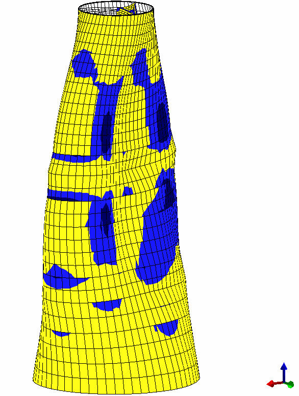
The analysis assumed in a first approximation that the cracks result from strainer vibration. A finite element (FE) model of the strainer was built in FE/Pipe from the strainer drawings. Because the shell is perforated, it was modelled as a continuous plate with reduced stiffness, following ASME B&PV Section VIII, Division 2, Appendix 4, Article 4-9. This gives an effective elastic modulus of 70,272 MPa, which is 0.36 times the modulus of solid Werkstoff 1.4571 (195,200 MPa). The same appendix indicates the stress intensification factor to use when evaluating the stresses calculated on the continuous plate: at least 5.87. Natural frequencies and mode shapes were calculated for the reinforced strainer (Figure 1) and, for reference only, for the unreinforced strainer.
Three mechanisms were examined. The first was mechanical resonance: the small amplitude flow and pressure oscillations that the compressor introduces on its suction side could excite a vibration mode of the strainer. The second was acoustic resonance: the same oscillations could create standing pressure waves in the pipe between the compressor suction nozzle and the strainer, resulting in large amplitude pressure excitation at the strainer. The third was oscillatory buckling: the pressure drop across the strainer creates a buckling load on the shell, and if the strainer external pressure capability is limited, flow fluctuations could create oscillatory buckling. This could generate high oscillatory bending stresses that result in fatigue.
Modal, Acoustic and Buckling Assessments
The compressor operates at around 6,000 rpm, a basic frequency of 100 Hz. The first stage at the suction side has 17 blades, so the blade passing frequency is 1,700 Hz. The reinforced strainer has 20 natural frequencies below 1,000 Hz, the lowest at 463 Hz. This is far above the basic compressor frequency and well below the blade passing frequency, so the modal results show no clear and distinct cause for resonance. Near the blade passing frequency, many mode shapes lie in a relatively small frequency band, and the calculation model is less accurate. There is a large probability that the blade passing frequency excites one of these high frequency modes, in particular if the compressor speed is varied. Vibration amplitudes will be limited because the modal stiffness of these modes is relatively high, but the stress levels may still be in the fatigue range. The harmonic analysis below returns to this point.
Acoustic resonance was assessed for the 26.9 m pipe section between the compressor suction nozzle and the strainer. At the design pressure of 52 Bara and temperature of 23°C, the speed of sound is 448 m/s, so the first half-wavelength standing wave has a frequency of 8.3 Hz, well below the blade passing frequency. Higher harmonics will be present in the blade passing frequency range. Standing waves at these frequencies over this length would have a large radiation effect in the audible range and would be observed at site. Nothing of this kind has been reported from site, so this mechanism was eliminated.
For buckling, the pressure drop across the strainer at design conditions was calculated as 0.99 Bar, using published correlations for perforated plates. An external pressure difference of 1 Barg applied to the reinforced strainer model gave nominal stresses of the order of 5 MPa. With the stress intensification factor of 5.87, the peak stresses are of the order of 35 MPa, well below the fatigue limit for stainless steel in ASME B&PV Section VIII, Division 2, Appendix 5. The minimum buckling factor with respect to this pressure is 40. Correcting for geometrical and material asymmetries with an assumed factor of 4 still leaves a safety factor of 10 against buckling. This mechanism was therefore eliminated.
Harmonic Response at the Blade Passing Frequency
The harmonic analysis of the reinforced strainer applied a fixed pressure amplitude of 1 Bar, selected arbitrarily, at excitation frequencies from 1,650 to 1,730 Hz in steps of 10 Hz. As fatigue is the problem, attention was focused on the peak stress amplitude at the outside of the strainer, evaluated according to ASME B&PV Section VIII, Division 2. For the 1 Bar amplitude it varies from 43 MPa at 1,650 Hz to 241 MPa at 1,690 Hz and back to 25 MPa at 1,720 Hz. Because the model is linear, these values were scaled to a pressure amplitude of 0.1 Bar, and the stress intensification factor of 5.87 was taken into account. Figure 2 shows the result.
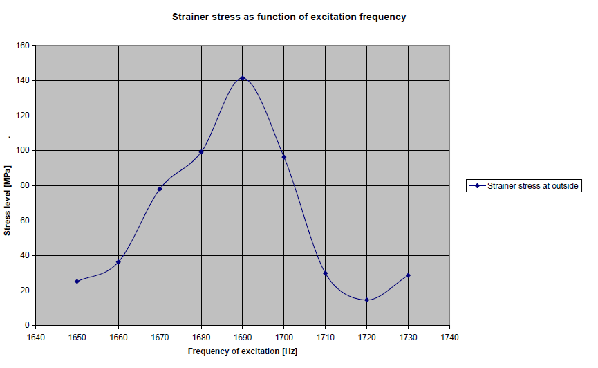
At a pressure amplitude of 0.1 Bar, the stress fluctuations are in the fatigue range for stainless steel type materials. The steady pressure drop across the strainer is around 1 Bar and is proportional to velocity squared, so a pressure drop of 0.1 Bar can be generated by a velocity fluctuation of 5 percent. It seems realistic that velocity fluctuations of a few percent at the blade passing frequency occur during normal compressor operation.
Blade Passing Excitation and Strainer Stiffening
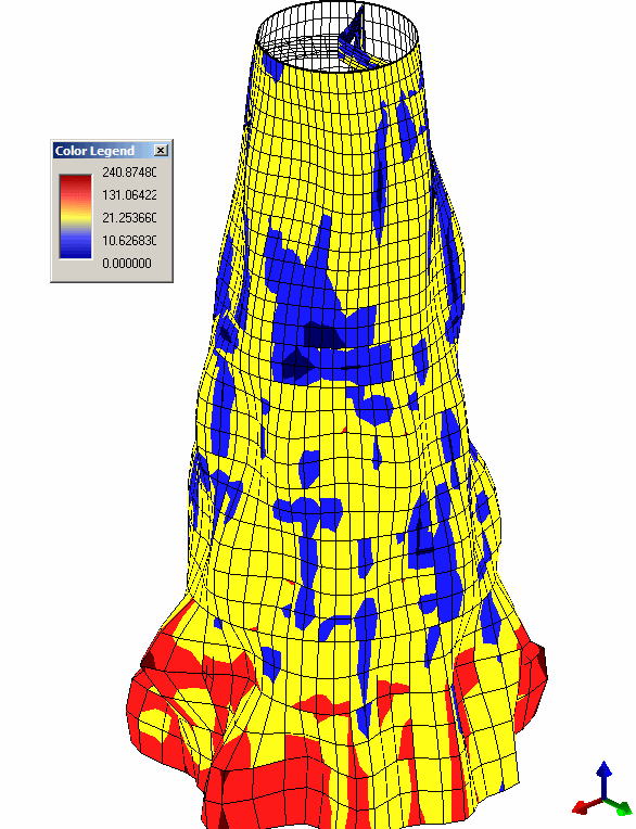
The FE results rule out oscillatory buckling, and acoustic standing waves were eliminated because no audible radiation has been reported from site. Normal pressure and flow oscillations at the blade passing frequency are a possible source of the observed fatigue. Figure 3 shows the peak stress amplitude on the outside of the reinforced strainer at 1,690 Hz for a pressure amplitude of 1 Bar. Eliminating the problem is not simple. It requires either removing the flow and pressure oscillations at the strainer or raising the strainer natural frequencies substantially.
Stiffeners in both axial and circumferential directions raise the lowest natural frequency from 346 Hz for the unreinforced strainer to 463 Hz for the reinforced strainer. Raising the natural frequencies above the blade passing frequency seems not realistically feasible, since substantial stiffening is required. Only when the natural frequencies are above the blade passing frequency is coincidence between a strainer mode and the blade passing frequency eliminated, also when the compressor speed is varied.
Frequently Asked Questions
What causes fatigue cracking in a perforated compressor suction strainer?
In this case study, normal pressure and flow oscillations at the blade passing frequency are a possible source of the observed fatigue. The FE analysis ruled out oscillatory buckling, and acoustic standing waves were eliminated because no audible radiation has been reported from site.
How is a perforated plate modelled in finite element analysis?
The perforated shell is modelled as a continuous plate with reduced stiffness, following ASME B&PV Section VIII, Division 2, Appendix 4, Article 4-9. This gives an effective elastic modulus of 70,272 MPa for Werkstoff 1.4571, which is 0.36 times the modulus of the solid material (195,200 MPa). The stresses calculated on the continuous plate are then evaluated with a stress intensification factor of at least 5.87.
What is the blade passing frequency of a compressor running at 6,000 rpm with a 17-blade first stage?
1,700 Hz. The compressor in this case operates at around 6,000 rpm, a basic frequency of 100 Hz, and the first stage at the suction side has 17 blades.