
A new natural gas booster plant at Winksele, Belgium, was undergoing Site Approval Tests (SAT) after the end of construction. The SAT scope included a pipe vibration level assessment to verify that all vibration levels were within acceptable limits. This case study describes the measurement campaign and the VDI 3842 assessment of the above-ground suction and discharge lines. This is a preliminary account: measurements had been performed for compressor trains 1 and 3 only.
Plant Layout, SAT Scope and Vibration Sources
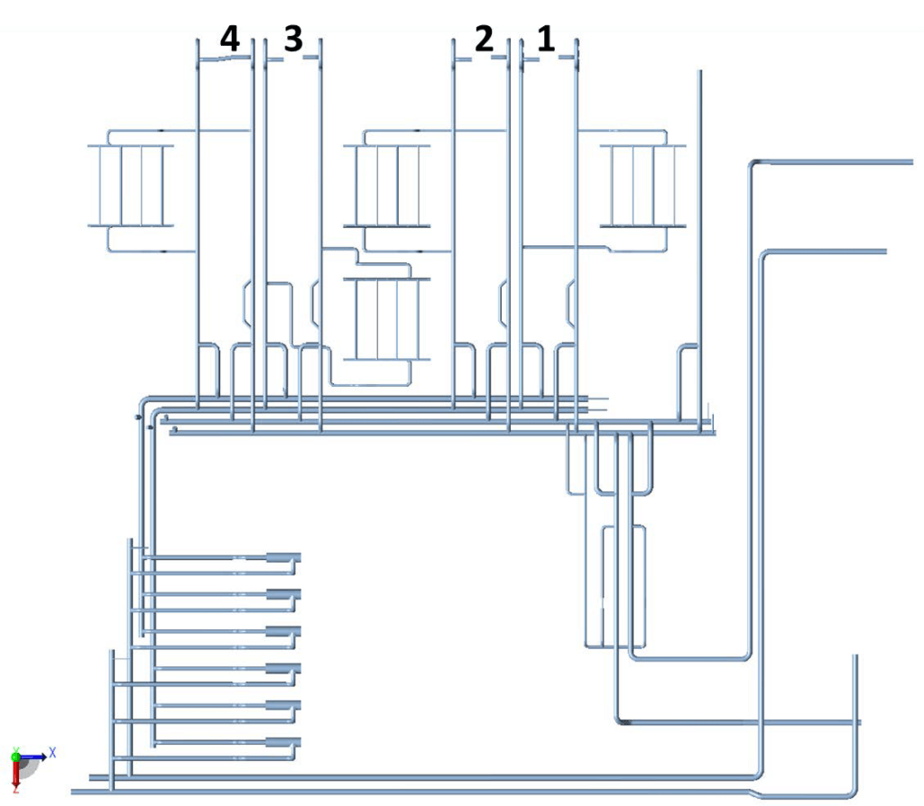
The plant has four compressors connected in parallel. The booster system also includes four fan coolers and six gas filters. The four compressor trains are almost identical. The only differences are in the lines to and from the cooler banks and the point where these lines tie in. The filters are located remotely. The assessment covered the above-ground suction and discharge lines close to the compressors, the coolers and the filters. During SAT the plant can be connected to the external grid, but flow can also be directed over the cooler banks, so both conditions can be taken into account during vibration measurements.
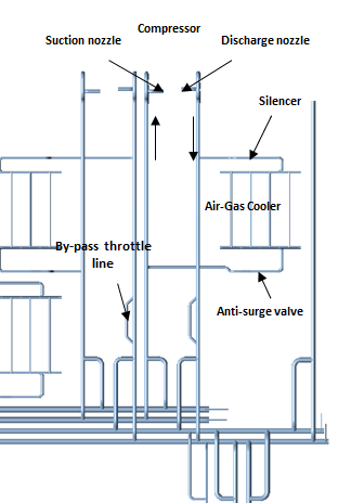
The piping has eigenmodes that may be excited by mechanically imposed vibration or by flow pulsations. Mechanically imposed vibration has a frequency equal to the compressor RPM. Imperfections in the compressor, such as small defects, fouling or misalignment of the axis to the motor, can generate mechanical vibration that is imposed on the piping. The motor can also generate mechanical vibration, although this is less likely to be passed to the piping. Vibration can be expected at the operating frequency and at multiples of it. The compressor impeller runs at 3500 to 6000 RPM (58 to 100 Hz), with a rated speed of 5864 RPM. The fixed gear ratio between the compressor and the driving motor is 3.26. Mechanical vibration from the compressor can only excite the piping close to the compressor, which is the elephant ear piping.
Flow pulsations can occur at the compressor blade frequency. With 19 blades per compressor, this frequency is in the range of 1100 to 1900 Hz. These pulsations can be magnified by acoustic resonance, which depends on the layout of the complete plant piping. Mechanical resonance in response to acoustic resonance typically results in breathing modes or pressure fluctuations at stub ends. Excitation of lateral pipe modes (beam modes) at such high frequencies is not likely. Flow-induced vibration may also occur at other frequencies due to surge phenomena. Flow-induced vibration may also occur at locations remote from the compressor.
VDI 3842 Assessment Method and Measurement Points
The assessment followed VDI 3842, which covers the evaluation of pipe vibration. A vibration measurement is taken, and a Fourier transform converts the acceleration versus time signal into an acceleration versus frequency signal. That signal is converted into a velocity versus frequency signal, which is plotted in the VDI 3842 assessment graph and compared with the graph lines. The graph has four lines, labelled design, marginal, correction and danger, each indicating the severity of the measured vibration.
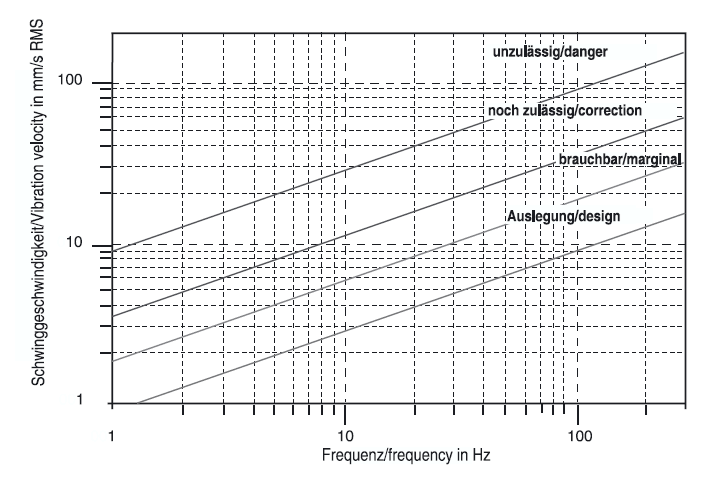
The lines are based on decades of experience with piping systems and apply to typical piping systems. They should not be interpreted as an absolute conclusion about severity. A very flexible piping system can deal with higher vibration levels than a stiff system, which the graph does not account for. VDI 3842 nevertheless gives a good picture of the severity of the vibrations. The assessment covers lateral pipe vibration, and the acceptable levels are defined such that pipe stresses are expected to stay within acceptable limits. The acceptability of frames and nozzles is not covered, including the compressor suction and discharge nozzles.
Measurement points were selected during a site visit at a sufficient distance from fixed points such as supports and underground connections. Deflections are larger at points away from fixed points than at points closer to them. Practical considerations were also taken into account. The lines are insulated for the most part, and measurement points were taken on small purge valves, flanges and similar features that are not insulated.
Vibration Data Acquisition and Processing
Measurements were carried out on three days. An acceleration transducer connected to the piping by magnetic coupling measures accelerations in three directions simultaneously. A three-channel connection to a Svantek 958 Sound & Vibration Analyzer registers the complete vibration in a single measurement and retains the time dependency between the movement in the three directions. Photographs and notes were taken for each measurement so that each of the three signals could be traced back to the direction of pipe movement (axial, vertical or horizontal) and the plotted results labelled correctly.
Within 0.5 to 12,000 Hz, the measured accelerations have an accuracy of 1 dB. The transducer was calibrated in July 2013 in accordance with ISO 16063-21:2003. The analyser registers up to 48,000 Hz, which is more than sufficient for these measurements.
SvanPC++ was used to read the data stored on the measurement device. An in-house Python script performed a Fast Fourier Transform on the raw acceleration versus time data using scipy.fft from the SciPy library and produced a plot of RMS velocity against frequency. The velocity versus frequency results were plotted in VDI 3842 assessment graphs.
Velocity relates to acceleration through a factor that depends on the inverse of the frequency (1/f). At low frequencies this factor becomes dominant, which makes low-frequency results less clear, although peaks, if present, can still be observed. Noise is a dominant factor at low frequencies in the VDI 3842 assessment graphs. In the compressor operating frequency range, mechanically imposed vibration is not diluted by the 1/f factor.
Measurement Results for Compressor Trains 1 and 3
Vibration levels were generally below the VDI 3842 assessment lines. Levels were very low at the filters and reasonably low at the cooler lines. Levels were highest at the lines close to the compressor. Peaks were visible at the compressor RPM, but these peaks were not high and were well within acceptable values in accordance with VDI 3842.
One exception was observed at compressor train 3: a high vibration level at 1 Hz on the discharge piping, at a location downstream of the elephant ear. The motor RPM, compressor RPM and compressor blade frequency are all much higher than 1 Hz, which eliminates them as the cause. No explanation had been found at the time of writing, since there is no obvious vibration source at 1 Hz.
Scope of VDI 3842 and the Open 1 Hz Finding
VDI 3842 assesses lateral pipe vibration. Frames and the compressor suction and discharge nozzles are not covered by the assessment. The 1 Hz level on the discharge line of compressor 3 is the exception to the finding that the levels close to the compressor are generally within the VDI 3842 acceptability limits.
Frequently Asked Questions
What does VDI 3842 cover when assessing pipe vibration?
VDI 3842 assesses lateral pipe vibration. Its acceptable levels are defined so that pipe stresses are expected to stay within acceptable limits. The acceptability of frames and nozzles is not covered, including the compressor suction and discharge nozzles. The lines in the assessment graph apply to typical piping systems, so they should not be read as an absolute conclusion about severity.
How is measured pipe vibration compared with the VDI 3842 lines?
An acceleration transducer on the pipe records the vibration in three directions at the same time. A Fourier transform converts the acceleration versus time signal into an acceleration versus frequency signal, which is then converted into a velocity versus frequency signal. The velocity signal is plotted in the VDI 3842 assessment graph and compared with its four lines: design, marginal, correction and danger.
Can compressor speed or blade frequency cause 1 Hz vibration on discharge piping?
No. On the discharge piping of compressor train 3, downstream of the elephant ear, a high vibration level was observed at 1 Hz. The motor RPM, compressor RPM and compressor blade frequency are all much higher than 1 Hz, which eliminates them as the cause. No explanation had been found at the time of writing.