
During re-alignment of the suction and discharge piping for sales gas compressors K2002A and K2002B, ready for connection to the compressor nozzles, the discharge line of K2002B could not be correctly aligned. The displacement at constant load hanger 04-SS-1017 (PS 1017) took the hanger out of its operating range.
A field check showed that a load of 41990 N (4280 kg), or 42.0 kN, was required at the PS 1017 location to bring the line into alignment. The hanger spring constant load is 29836 N. The hanger had also been moved 770 mm from its original as-built position. Advice was required on the next step to solve the alignment issue.
CAESAR II Model of the Discharge Line
The investigation started with a CAESAR II model of the K2002B discharge line. The model was built from the as-built isometrics and extends to support 04-PS-3035. It includes the weight of the insulation, the function of each support and the thermal expansion of the compressor at the discharge nozzle, taken from the compressor datasheets.
The insulation on the 16 inch discharge piping was modelled as two 50 mm layers of Rockwool mineral wool, a 5 mm barrier material and a 2 mm layer of Ulva cladding. The mineral wool was given 120 kg/m³, the mean value for mineral wool insulation in the insulation specification. The barrier material was assumed to have a similar density, and the cladding was given 850 kg/m³.
The line has a hot design temperature of 240°C and a maximum design pressure of 98 barg. The isometrics state carbon steel, and the properties were taken as ASTM A106 Gr. B, with a modulus of elasticity of 203 GPa, a cold allowable of 138 MPa and a hot allowable of 133 MPa.
To simulate the alignment situation, the flange connecting to the discharge nozzle was set as a free end. With the original design cold loads on the hangers (29836 N at PS 1017, 18385 N at PS 1014 and 45172 N at PS 1019), the connecting flange sagged 110 mm below the nozzle. The displacement at PS 1017 was 80 mm, outside its permitted travel.
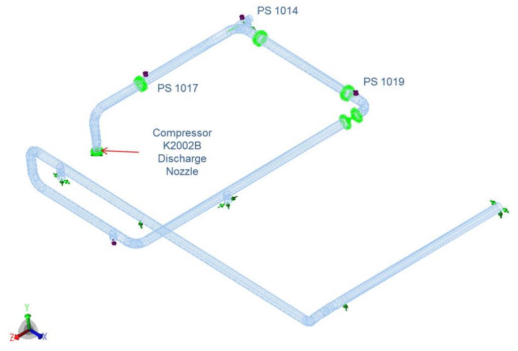
Hanger Options for Aligning the Nozzle
Option 1 replaced only constant load hanger PS 1017 with one of higher load. In the model, a hanger load of 29836 N gave a nozzle displacement of 110 mm, approximately 38.2 kN aligned the nozzle in the vertical direction, and 42.0 kN gave a misalignment of 51 mm.
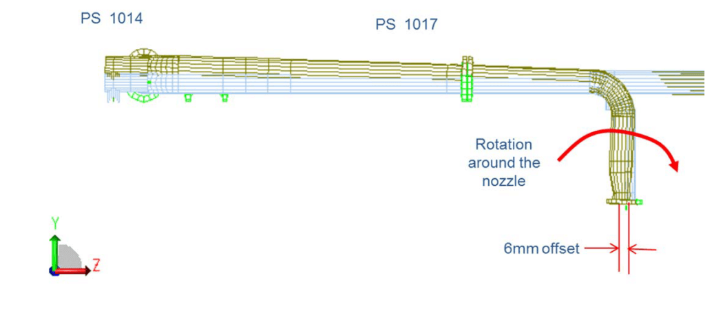
At 38.2 kN, a 6 mm misalignment remained in the horizontal direction, and the nozzle loads in the sustained load case exceeded the API 617 allowable values for a single nozzle.
Option 2 changed two hangers together. PS 1017 was set at a constant load of 40300 N. PS 1014 was replaced with a Bergen Pipe Support Variable Effort Support Type V3-21, with a cold installation load of 14400 N and a spring rate of 70.7 N/mm. The two hangers were sized so that no vertical height differential remains between them. The manufacturer was chosen for consistency with the existing hangers.
Changing PS 1014 as well as PS 1017 is necessary to keep the discharge nozzle loads within the API 617 allowable values. PS 1014 had been designed for the situation before PS 1017 was moved by 770 mm.
Nozzle Load, Stress and Flange Results
The revised configuration was assessed against API 617 for nozzle loads, ASME B31.3 2010 for piping stress and flexibility, and ASME B16.5 for flanges. In the API 617 single nozzle check, the loads reached 21% of the allowable resultant nozzle load in the sustained load case and 40% in the hot design load case.
The sustained load case (W+D2+P1+H) combines the weight loads, the compressor nozzle displacement when cold at 20°C, the design pressure and the hanger loads. The hot design load case (W+D1+T1+P1+H) uses the compressor nozzle displacement in operation and adds the hot design temperature.
Two further API 617 checks combine the loads from the suction and discharge nozzles. With discharge nozzle loads only, the combined individual component check gave 26% and 56%, and the combined allowable resultant nozzle load check gave 29% and 63%, for the sustained and hot design load cases respectively. All of these values are within the allowable.
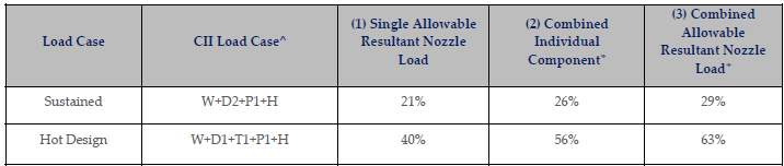
The suction nozzle loads were not available, so the combined checks could not be completed in full. The analysis considers it reasonable for the discharge nozzle loads not to exceed 50% of the total allowable combined load. In the hot design case, both combined checks exceed 50% with discharge nozzle loads alone, so it is not certain that there is sufficient margin for the suction nozzle loads. To be certain of conformance with API 617, the suction nozzle loads should be included in the assessment.
All stresses in the discharge line near the discharge nozzle conform with ASME B31.3 2010. The flanges near the nozzle conform with an equivalent pressure check to ASME B16.5. The variable hangers remain close to their cold installation load and within their operating range at hot design.
Hanger Relocation and the Field Check Load
With Option 1, the line is inclined to the horizontal between the nozzle and the elbow at PS 1014. The 6 mm horizontal misalignment is attributed to PS 1014 being set for too large a load. The sustained case exceedance is predominantly due to the moment about the X axis, which is consistent with the rotation around the nozzle shown in the figure.
The 40.3 kN constant load required in the analysis is within 10% of the 42.0 kN from the field check, with a new variable hanger at PS 1014 in the model. The available information does not explain why 42.0 kN was required.
If desired, a larger constant load hanger could be ordered and additional weights added as necessary. If the required load deviates significantly from 40.3 kN, the API 617 nozzle load check must be re-evaluated.
Frequently Asked Questions
What load is needed on a constant load hanger to align a compressor discharge nozzle?
The model gave approximately 38.2 kN for vertical alignment, and 40.3 kN with a new PS 1014 variable hanger. The field check gave 42.0 kN.
What did the API 617 single nozzle check show after changing both hangers?
21% of the allowable resultant nozzle load in the sustained case and 40% in the hot design case.
Why could the combined API 617 nozzle load check not be completed?
Suction nozzle loads were not available. With discharge nozzle loads alone, the hot design combined checks give 56% and 63%.