
Surge loads from deluge valve closure were applied to nine composite firewater deluge systems in a CAESAR II time-history analysis and checked as occasional stresses against the ISO 14692 envelope. With three axial stops added in S4, all stress points lie within the envelope; the highest of the nine Smax values was 32.5 MPa at an elbow node.
Deluge valve closure loads on a firewater system extension
A gas flow station was to be upgraded to increase marketable gas production, and the existing firewater system was to be extended as part of the upgrade. Stress analyses were performed for parts of the upgraded system: nine deluge systems, designated S1 to S9, and four smaller sections, designated together as system T. The dynamic assessment covered deluge systems S1 to S9.
Each deluge system has two deluge valves. An earlier surge analysis had examined the firewater scenarios, which involved opening and closing of the deluge valves. It found that the unbalanced loads from rapid opening were relatively mild, a consequence of the dissipative nature of the deluge valve. Fast closing of a deluge valve at the end of a fire alarm, however, could result in time-dependent loads that needed further consideration.
A static stress analysis had already been performed for the upgraded system. The dynamic assessment is an addendum to it and evaluates the stresses and restraint loads that arise when the deluge valves close.
BOSfluids surge loads in a CAESAR II time-history model
The unbalanced loads were extracted from the BOSfluids surge analysis results and applied to the corresponding pipe sections in CAESAR II. The dynamic calculations were performed with the CAESAR II time-history dynamic module. The models were those constructed for the static stress analysis, adjusted where the dynamic results made it necessary.
The loads depend on the closing curve, which describes the relation between time and valve opening. A more abrupt closure produces higher pressure peaks and higher unbalanced loads, while a gradual and slow closure produces smaller pressure peaks and loads. The dynamic loads were calculated with a conservative, unfavourable closing curve, in which the majority of the cut-off occurs right after the valve starts to close, and a closing time of 1 second per inch of valve size.
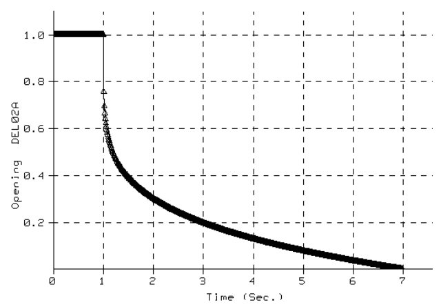
Because the loads from closing either valve in a system are comparable, stresses were computed for the loads from one valve per system, designated valve A.
Occasional stress check against the ISO 14692 envelope
The dynamic stresses were assessed as occasional stresses. The dynamic stress was combined with the sustained static stress, and the combination was tested against a simplified stress envelope for occasional load according to ISO 14692. The envelope is plotted as combined axial stress against hoop stress.
The sustained load case contained the weight of the pipe and contents and the internal pressure, with the operating pressure selected as the sustained pressure. A pressure of 7 barg was used. The report describes this value as conservative but realistic and much lower than the design pressure, and bases it on the maximum pressure of 5 barg seen in the deluged system.
In an earlier analysis phase, high surge loads at typical locations had already been anticipated by introducing axial stops at those positions. The report states that the modifications required by the dynamic analysis were therefore very limited in number. Any modification based on the dynamic analysis affects the static stress analysis, and the reverse also applies, so the dynamic and static analyses were reiterated to verify the fitness for purpose of the proposed modifications both dynamically and statically. The reported results are those of the final iteration.
Stress and restraint load results for deluge systems S1 to S9
After the final iteration, all stress points for systems S1 to S9 lie within the ISO 14692 occasional stress envelope. For each system the report gives Smax, the stress that is largest with respect to the allowable. The highest of the nine Smax values was 32.5 MPa at an elbow node in S8, followed by 32.3 MPa at an elbow node in S1. The lowest of the nine was 16.5 MPa at a 150×150 tee in S9.
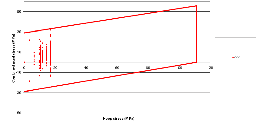
S4 was the only system that required modification. Axial stops were added at three nodes, 1250, 1400 and 4030, to reduce stresses to within the envelope, and the S4 Smax was 31.0 MPa at an elbow node. For the other eight systems, no modifications such as extra supports or laminate reinforcements were required.
| System | Smax (MPa) | Location | Modification |
|---|---|---|---|
| S8 | 32.5 | Elbow node | None |
| S1 | 32.3 | Elbow node | None |
| S4 | 31.0 | Elbow node | Axial stops at nodes 1250, 1400, 4030 |
| S9 | 16.5 | 150×150 tee | None |
The largest of the tabulated restraint load components was 17,353 N in the Y direction at a 3-way stop in S4. The report notes that because the unbalanced loads are largest on long pipe segments, the highest support loads occur at those segments. All required modifications were marked up on the stressed isometrics of the static stress report.
Deluge valve closing curve recommendation
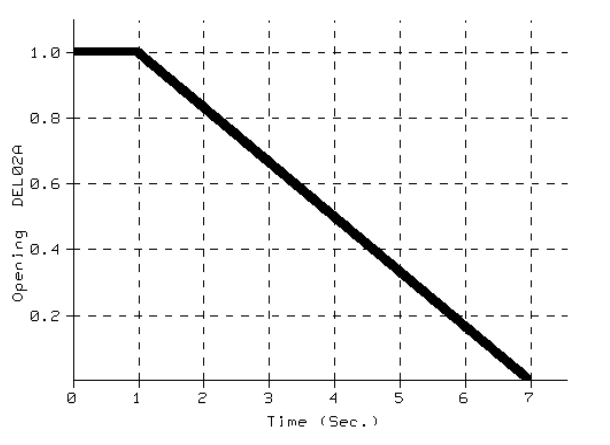
The analysis was performed for the conservative closing curve. As explained in the report, and in more detail in the surge analysis, a more favourable closing curve for the deluge valves will result in lower unbalanced loads, lower stresses and lower support loads. The report strongly recommends imposing more favourable closing curves on the deluge valves, and it shows a linear closing curve as a suggested closing curve.
In sequence, surge loads computed in BOSfluids were applied to the static CAESAR II models in a time-history analysis. The dynamic stress was then combined with the sustained stress and checked as an occasional load against the ISO 14692 envelope. Finally, the dynamic and static analyses were reiterated to verify the fitness for purpose of the modifications.
Questions on surge loads and ISO 14692 occasional stress
How are surge loads applied in a CAESAR II time-history analysis?
In this project the unbalanced loads were extracted from the BOSfluids surge analysis results, applied to the corresponding pipe sections in the CAESAR II models built for the static stress analysis, and solved with the CAESAR II time-history dynamic module.
How is dynamic stress assessed under ISO 14692?
The dynamic stresses were assessed as occasional stresses. The dynamic stress was combined with the sustained static stress and tested against a simplified stress envelope for occasional load according to ISO 14692, plotted as combined axial stress against hoop stress.