
Why Pulsation Risks Warranted Attention Before Operation
The compression station was designed to increase and maintain operating pressure on a natural gas piping network, overcoming friction losses. It has four (3+1) two-stage centrifugal compressors with 19-blade impellers, running at a rated speed of 5750 RPM (95.8 Hz) within a range of 3675 to 6342 RPM. Such machines produce a periodic, low-amplitude pressure and flow oscillation at the blade passing frequency, which for this impeller lies between 1163 and 2008 Hz, with a rated value of 1820 Hz.
Acoustic resonance occurs when the frequency of a pressure pulsation equals an acoustic natural frequency of the pipe. Originally low pulsation levels can then be amplified to high amplitudes, which can lead to noise and excite structural vibration. Pressure pulsations also generate unbalanced loads on the piping. Radial pipe wall vibration, also called a breathing mode, is particularly evident in large-diameter thin-walled pipe and can cause significant noise levels and acoustic fatigue.
Problems caused by compressor-induced pulsations tend to be discovered and fixed only during operation. This study aimed to identify potential pulsation and vibration issues before operation. It gave particular attention to acoustic standing waves in stub ends and to the above-ground spiral-wound piping attached to the compressor nozzles, known as elephant-ears.
Analysis Methods for Pulsation and Structural Vibration
The assessment followed VDI 3842, a guideline that leaves room for the engineer’s interpretation. Most of it addresses reciprocating equipment, so it was used for its general directions only. The pulsation limits it prescribes for reciprocating compressors are not very relevant to centrifugal compressors, and API 617 sets no pulsation limits comparable to those in API 618.
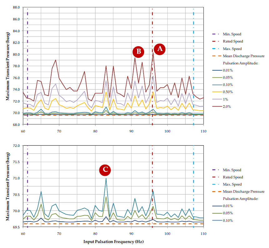
The work had three parts: a pulsation study, a low-frequency structural vibration analysis and a high-frequency structural vibration analysis. The pulsation study used one-dimensional transient flow simulations in BOSfluids for all piping larger than 3 inches. It covered two frequency bands. The first is the compressor speed range, where pulsations in principle should not occur but might be caused by slight impeller imbalance or asymmetric impeller geometry; their consequences were verified regardless. The second is the blade passing range. The compressor vendor supplied no data on pulsation amplitude, so harmonic pressure excitations were applied at the suction and discharge nozzles over a range of amplitudes. In the speed range (61 to 106 Hz, 1 Hz increments), six mean-to-peak amplitudes from 0.01% to 2% of the mean suction and discharge pressure were used. These cover the VDI 3842 limit of 1.8% mean-to-peak for two-stage compressors, and 0.01% was considered the most realistic for a centrifugal compressor. In the blade passing band (1163 to 2008 Hz, 10 Hz increments), amplitudes of 0.01%, 0.05% and 0.1% were used, because larger amplitudes were not considered realistic.
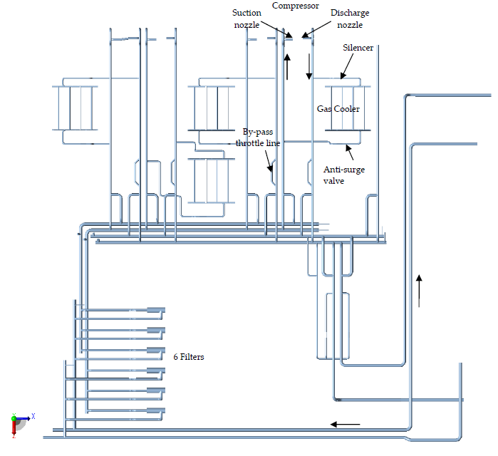
Suction and discharge gas properties differ, so separate suction and discharge acoustic models were used. Each was run for the parallel and dissimilar normal operating modes and for two sets of gas process conditions, with acoustic velocities of 431 m/s (Normal 1) and 459 m/s (Normal 6). Not all valve combinations were simulated; attention was given to covering all combinations of lengths between reflection points (closed valves, bends, tees, reducers), so as not to miss important acoustic natural frequencies. In total, more than 4200 transient simulations were run on an 8-core workstation.
Low-frequency flexural, longitudinal and torsional modes of the elephant-ears and their steel frames were modelled in CAESAR II with three-dimensional beam elements. The nozzle flanges were excited harmonically from 61 to 108 Hz in 1 Hz increments, individually in the x, y and z directions, at an amplitude of 0.1 mm taken from the permissible pipe vibration graph in VDI 3842. Beam elements cannot capture breathing modes, and the shell-element package FE/Pipe cannot cover 1163 to 2008 Hz computationally, so breathing mode frequencies were estimated with Donnel’s theoretical shell model, which is valid for simply supported shells. Acoustically induced fatigue at a transient pressure amplitude of 2.5 bar was assessed using the acoustic power level according to Carucci and Mueller against Eisinger’s allowable design limit. A conservative harmonic model of the above-ground elephant-ear assessed unbalanced forces between elbow pairs at blade passing frequencies.
Transient Pressure, Structural Response and Fatigue Results
Resonant peaks appeared in all sweeps, and avoiding all acoustic resonance is difficult over wide frequency ranges in a complex system. For pulsation amplitudes of 0.1% or below, the additional transient pressures did not exceed 2.5 bar; at 0.01% they did not exceed 0.5 bar. On the discharge side, resonance recurred in the closed by-pass throttle lines and in closed sections of the 20-inch dam lines. On the suction side it recurred in the 20-inch cooler outlet lines. The same sections resonated at different frequencies for different gas process conditions and valve combinations, so the transient response is sensitive to both. No resonance was observed in the cooler inlet lines on the discharge side, which are truncated at silencers modelled to damp pulsations without reflecting them. The closed anti-surge valves on the suction side reflect pulsations.
Harmonic nozzle excitation amplified the input displacements by up to four times. The maximum calculated dynamic stress in the elephant-ear piping was 7.2 MPa, at 80 Hz on the discharge side for excitation in the z-direction. This is below the endurance limit on the ASME B&PV Section VIII Division 2 fatigue curve for an infinite number of cycles. On this basis it was decided not to modify the elephant-ear supports or the frame. Donnel’s model was applied to a 30-inch pipe with lengths of 1.5, 2.0 and 3.0 m and wall thicknesses of 14.7 and 17.7 mm. Each combination has at least 25 breathing modes between 1150 and 2060 Hz. The model indicates how many modes lie in this range; it is not accurate enough for exact frequencies. The uniform radial mode of an infinitely long pipe, at around 2100 Hz, lies above the upper bound of the blade passing range.
For a transient pressure amplitude of 2.5 bar in the discharge compressor line (5 bar peak-to-peak), the acoustic power level was 147.2 dB. Eisinger’s allowable limit is 173.6 minus 0.125 times the ratio of external diameter to wall thickness, which gives 167.1 to 169.0 dB for the 40, 36, 30 and 20-inch sections where resonance with transient pressure amplitudes was found. No acoustically induced fatigue is expected.
In the elephant-ear unbalanced force model, a pressure difference of 2.5 bar (2 × 1.25 bar) was applied on all pipe sections between two elbows, across 1163 to 2008 Hz. The 1.25 bar is the maximum transient pressure amplitude simulated near the elephant-ear at high frequency, for a 0.1% disturbance. The maximum dynamic code stress was below 30 MPa and did not occur in the elbows. With a maximum below 30 MPa, the ASME B&PV Section VIII Division 2 fatigue curve is not exceeded for any number of cycles. Compressor-induced pulsation amplitudes of 0.1% or less of the mean suction and discharge pressure are therefore acceptable for the piping.
Short Closed Sections, Model Dimensions and Elephant-Ear Modes
Resonance occurred more often in short sections and in sections closed at one end than in longer sections. This can be attributed to higher damping from wall friction in longer sections. In the blade passing band the pulsation wavelengths are in the order of 200 to 300 mm, so the results depend on the model dimensions. The dimensions of the real system have to match the isometrics used for the models.
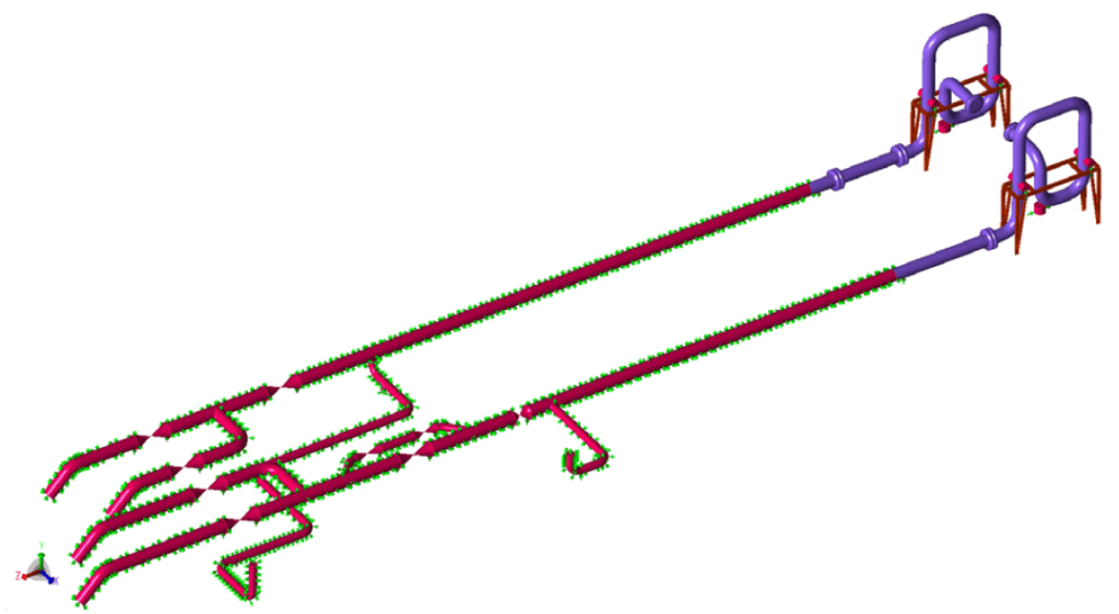
Higher order flexural modes of the elephant-ears lie within the 61 to 108 Hz range of the nozzle excitation and interact with the frames. Stiffening the elephant-ears and frames would only shift lower order modes into that range. A trial of increased frame stiffness led to increased piping vibration at almost similar frequencies, because the frame no longer absorbed kinetic energy. Two suction side natural modes, at 96.5 and 100 Hz, lie just above the rated speed, and the pulsation study indicated possible transient pressure amplification on the suction side at 94, 95 and 104 Hz. Unbalanced forces from these pressures might excite those modes, but compressor-induced pulsations are not expected at these frequencies unless the impeller is slightly imbalanced or damaged and has an asymmetric geometry.
Frequently Asked Questions
How do you choose pulsation amplitudes when the compressor vendor gives no data?
The study applied harmonic pressure excitations at the suction and discharge nozzles over a range of amplitudes. In the compressor speed range, six mean-to-peak amplitudes from 0.01% to 2% of the mean suction and discharge pressure were used, covering the VDI 3842 limit of 1.8% mean-to-peak for two-stage compressors. In the blade passing band, amplitudes of 0.01%, 0.05% and 0.1% were used, because larger amplitudes were not considered realistic.
Do VDI 3842 pulsation limits apply to centrifugal compressors?
They are not very relevant. VDI 3842 is a guideline that leaves room for the engineer’s interpretation, most of it addresses reciprocating equipment, and the pulsation limits it prescribes are for reciprocating compressors. API 617 sets no pulsation limits comparable to those in API 618. The study therefore used VDI 3842 for its general directions only.
Is acoustic fatigue expected from pipe wall breathing modes in compressor piping?
No acoustically induced fatigue is expected for a transient pressure amplitude of 2.5 bar. The acoustic power level was 147.2 dB, against Eisinger’s allowable limit of 167.1 to 169.0 dB for the 40, 36, 30 and 20-inch sections where resonance with transient pressure amplitudes was found. The limit is 173.6 minus 0.125 times the ratio of external diameter to wall thickness.