
Flange Leakage in 44-Inch Catalytic Oxidiser Piping
The 44-inch top and bottom nozzles of a catalytic oxidiser are connected to the shell and tube sides of a recuperative heater by 44-inch piping. The hot design temperature is 527 °C. The required piping flexibility is provided by a number of expansion joints and spring-type supports. The client reported a number of flange leakages, which occurred in the flange joints of the piping to expansion joints LH-1817 A and B.
A site visit found that the recuperative heater was exposed to a large lateral load, which created a rotation of the heater around the vertical axis. The concrete support foundation showed cracks, and the sliding point of the heater showed a relatively large lateral displacement. One possible explanation for the leakages was unforeseen external flange loads, with a potential relation between large flange loads and the rotation of the heater.
CAESAR II Model, Calibration and Load Cases for Catox Piping
The static assessment used a beam element model built in CAESAR II from the received drawings. The model included the catalytic oxidiser, the recuperative heater, a segment of the gas heater and the interconnecting 44-inch piping. The three received models each covered a subsection of the system, whereas this model included all lines together, which allowed for interference between lines. Allowable stresses for A358 304 were used, because no allowable values were available for grade 304H.
Expansion joints were most often included as zero-length elements with the specified stiffness, and their weight was incorporated in the connecting rigid elements. Expansion joints LH-1817 A and B were modelled with overall lateral stiffnesses of 80.5 N/mm and 121 N/mm respectively, as stated on the drawings.
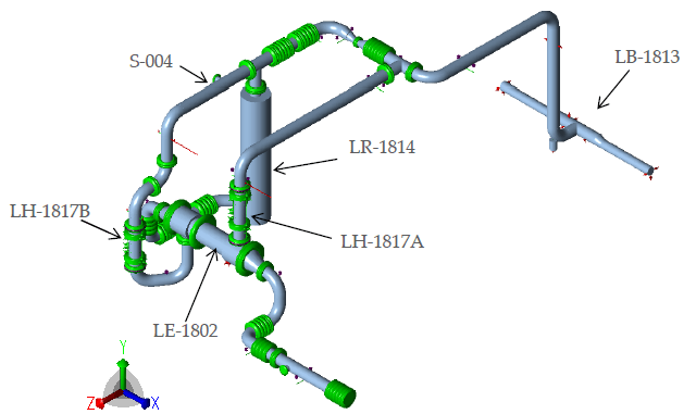
Hanger readings were obtained from photographs where legible, and the client supplied the measured displacements of the top and bottom flanges of LH-1817 A and B. Parameters such as the expansion joint stiffness and spring support properties were adjusted so that the calculated displacements matched the measured values as closely as possible, and were then varied to estimate the sensitivity of the results. Some calculated values differed from the measured values by more than 10%.
The calculated outcome is sensitive to several key parameters. The stiffness of the recuperative heater has a strong influence on the displacement of LH-1817 A and B and on the lateral load on the sliding support of the heater. With the stiffness from the supplier catalogue implemented for the hangers, the hanger displacements do not match the measured values. With the hangers treated as constant-load hangers, the hanger displacements match quite well, but the calculated displacements of LH-1817 A and B deviate strongly from the measured values. The implemented values were chosen to give the best match between the calculated and measured displacements for both the flanges and the hangers.
Seventeen load cases were defined: seven operating (L1 to L7), two sustained (L8 and L9), four occasional (L10 to L13) and four expansion (L14 to L17).
Static Stress, Heater Support Load and Flange Checks
For load cases L8 to L17, the highest ratio to the allowable stress is 282%, in sustained load case L8 (weight, the 140 mm lateral installation displacement of LH-1817 A, design pressure of 20 barg and hanger loads). This is a stress of 272.9 MPa at node 4320, in the 44-inch equal tee, modelled as a welding tee, that connects lines P-L1801501 and P-L1801502. The ratio corresponds to an allowable stress of 96.8 MPa, which is the hot allowable at 527 °C listed for the material. The primary stress exceeds the allowable at several locations along lines P-L1801501 to P-L1801504. Sustained case L9 reaches 238% of the allowable, occasional cases L10 to L13 reach 198% to 231%, and expansion cases L14 to L17 reach 8% to 65%. The hanger supports carrying lines P-L1801501, P-L1801502 and P-L1801503 lift the lines upwards, which causes high bending stress in the tees.
The tees were modelled with a wall thickness of 14.27 mm. The received models used 30 mm for the same tees. The received drawings do not specify the 30 mm thickness, but it is possible that it is implemented in the field. With 30 mm applied, all calculated stresses fall below the allowable except the sustained stress in load case L8 at node 4360, which is 104.5 MPa (108%). The 24-inch branch shown on the drawings is not included in the model, because its continuation is not known. If it has no vertical support close to the 44-inch header, its weight can influence the calculated results.
Field observations showed damaged concrete at the sliding support of the heater, indicating large lateral forces. Thermal expansion of line P-L1801506 results in a force in the north direction on this support. With the stiffness of the bellows in line P-L1801506 as stated on the drawings and no clearance, the calculated lateral force is 136 kN in operating load case L2. With an additional bellows stiffness of 19200 Nm/deg (1600 Nm/deg/bar at 12 bar operating pressure), which can be caused by friction in the hinges of the expansion joint, the calculated lateral force is 309 kN. The largest calculated lateral displacement of the heater from cold to hot is 19 mm, consistent with the shifting movement observed on site. Any clearance larger than this displacement results in zero lateral force. Friction loads are not completely reversible, so the final position of the heater after cooling and the remaining pipe stress in the cold condition are difficult, if not impossible, to determine.
Several flanges were checked in the CAESAR II model by comparing the equivalent pressure, calculated from the external forces and moments, with the allowable flange rating pressure in B16.47. For all load cases the equivalent pressure was below the allowable value. The maximum external loads in the operating case were a force of 146 kN and a moment of 69 kNm. No high equivalent pressure was found when displacements were imposed at nozzle N2 of the heater and at the top flange of LH-1817 B so that the calculated displacement of the bottom flange was similar to the measured value. With an additional stiffness of 19200 Nm/deg applied to each bellows of lines P-L1801505 and P-L1801506, the loads on the bottom flange of LH-1817 B were a force of 142 kN and a moment of 107 kNm, and again no high equivalent pressure was found.
The calculated loads are not large enough to cause leakage at all flange joints that have leaked. The outcome shows large scatter depending on the parameters varied. The steel frame of LH-1817 A and B restrains Fy, My and Mz, and no large My or Mz moments were found in the model. If these moments create large friction in the double hinges of the frame, the flexibility of the expansion joint reduces, which can lead to external moments above the calculated values.
Bolt and Flange Stresses from Axisymmetric FE Analysis
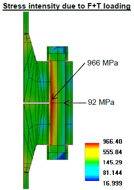
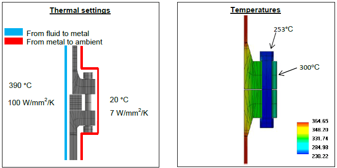
The bottom flange joint of LH-1817 B was modelled in AxiPRO as a 9° section with rotationally symmetric boundary conditions and one bolt. The model assumed 1¾-inch regular bolts, with no rotabolts present, and a clamped length of 257 mm. The flange material is A-182 F304H (hot yield stress 128.2 MPa at 304 °C) and the bolt material is A-453 660-B (hot yield stress 548.2 MPa at 253 °C). The bolt-up moment of 3876 Nm per bolt gives an axial force of 553.8 kN, calculated with ASME VIII-1 Appendix 2 rules. The thermal load used the maximum temperature difference between bolt and flange from the measurement data, 51 °C (flange 304 °C, bolt 253 °C). This maximum difference was found after heat-up and before the joint is insulated. No detailed transient thermal data was available.
Under bolt-up load alone, the largest calculated stress intensity in the bolt is 784 MPa (membrane 441 MPa, bending 343 MPa), which is above the bolt hot yield stress of 548.2 MPa. With the thermal load added it is 966 MPa (membrane 528 MPa, bending 438 MPa), and the membrane stress is close to, but below, the yield stress of 548.2 MPa. The bolt can show plastic bending, which can already occur under bolt-up load alone and becomes more severe with the thermal load. With modelling inaccuracies taken into account, stretching of the bolts is a plausible scenario.
Under bolt-up load, the tensile stress in the vertical direction (σy) in the flange hub exceeds the flange hot yield stress of 128.2 MPa, so the flange can show local plastic deformation. Stress components in the flange hub and blade were found to be above the flange yield stress and might cause deformation of the flange in the tangential direction, referred to as warping. If this occurs, the bolt tension redistributes over all bolts, the seating load reduces for some bolts, and local leakage can result at those bolts.
Plausible Cause of Flange Leakage and Recommendations
The analyses show that flange leakage cannot be explained by external loads on the flange joints. This holds for all variations applied to the model: the spring rate of the constant-load hangers, additional bellows stiffness from friction in the hinges of the expansion joints, variation of the hanger stiffness and variation of the clearance of the sliding support under the heater.
A plausible cause is stretching of the bolt due to the temperature difference between flange and bolt. This temperature difference is most likely greatest during startup. The calculation used the highest available temperature difference, and the resulting membrane stress of 528 MPa is below the bolt hot yield stress of 548.2 MPa, which means that the yield stress can be exceeded if higher temperature differences occur during the transient startup. After startup, the nuts of several bolts could be tightened with a relatively low bolting moment, which is a strong indication of bolt stretching.
Three recommendations follow. The actual thickness of the 44-inch equal tees should be checked to confirm the stress state. A clearance of around 2 to 3 cm at the sliding support of the heater is recommended to allow its lateral movement. The resulting slight rotation of the heater in the horizontal plane should be allowed by the fixed support on the west side of the heater. The bolt length should be increased, which increases bolt flexibility and reduces the bolt stress.
A total bolt length of 452 mm is calculated from the total stress (membrane plus bending) of 966 MPa, the hot yield stress of 548.2 MPa and an original length of 257 mm. Using the total stress makes this a conservative approach. This length would reduce the total stress to below the yield value, so that neither plastic bending nor plastic stretching of the bolt can occur.
Frequently Asked Questions
Can external loads on flange joints explain leakage at expansion joints in hot 44-inch piping?
In this assessment they could not. The calculated loads are not large enough to cause leakage at all flange joints that have leaked, for every model variation applied. In the operating case the maximum external loads were a force of 146 kN and a moment of 69 kNm, and for all load cases the equivalent pressure was below the allowable flange rating pressure in B16.47.
Can a temperature difference between flange and bolt cause bolt stretching and flange leakage?
The analysis found it a plausible cause. The model used a maximum bolt-to-flange temperature difference of 51 °C (flange 304 °C, bolt 253 °C), found after heat-up and before the joint is insulated. The largest calculated stress intensity in the bolt was 784 MPa under bolt-up load alone and 966 MPa with the thermal load added, against a bolt hot yield stress of 548.2 MPa. After startup, the nuts of several bolts could be tightened with a relatively low bolting moment, which is a strong indication of bolt stretching.
How much clearance does a recuperative heater sliding support need to remove the lateral load?
For this heater, the largest calculated lateral displacement from cold to hot was 19 mm, and any clearance larger than this displacement results in zero lateral force. A clearance of around 2 to 3 cm at the sliding support is recommended. Without clearance, the calculated lateral force on the support was 136 kN with the bellows stiffness stated on the drawings and 309 kN with an additional bellows stiffness of 19200 Nm/deg. The resulting slight rotation of the heater in the horizontal plane should be allowed by the fixed support on the west side.