Buried Fibreglass Piping and an Undefined Compression Envelope
The underground part of a seawater network at a gas field development was to be built in filament-wound fibreglass reinforced epoxy pipe buried in sand. The scope covered two systems, 1001 and 1002. Each system consists of a header of 54-inch and 32-inch piping, six gas treatment (GTU) trains and four sulphur recovery (SRU) trains. The scope also included small-bore 1-inch and 2-inch (DN50) piping.
The design conditions are:
- Design pressure: 14.5 barg
- Hydrostatic test pressure: 21.75 barg
- Design temperature underground: 55 degrees C (hot) and 5 degrees C (cold)
- Design temperature above ground: 85 degrees C (hot) and 5 degrees C (cold)
- Ambient (installation) temperature: 5 to 48 degrees C
- Seawater density: 1020 kg per cubic metre
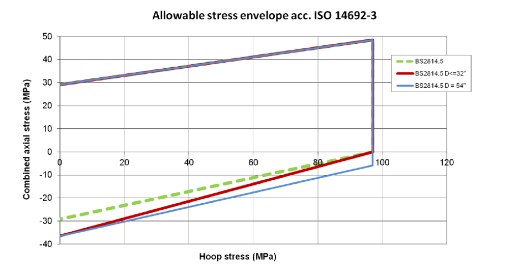
Compression stresses are largely present in buried piping. However, the issue of ISO 14692 current at the time did not prescribe the shape of the compression part of the allowable stress envelope.
The static stress analysis compared the computed stresses with allowable envelopes. It then recommended modifications to bring the stresses within the allowable limits, while keeping those modifications to a minimum at the current stage of design.
How the Network Was Modelled and Assessed
The analysis was carried out in CAESAR II. Existing mechanical piping models from the pipe supplier were updated to the latest isometric drawings. Pipe and fitting thicknesses were entered from the information received.
The soil reaction was modelled in accordance with the ASCE Guidelines for the Design of Buried Steel Pipe, using a soil density of 1900 kg per cubic metre and a friction angle of 36 degrees. The buried depth was computed from the grade levels and the pipe elevations on the isometrics.
Four load cases were analysed:
- Hydrotest: weight plus a hydrostatic pressure of 21.75 barg.
- Operational: weight, 55 degrees C and 14.5 barg, with an installation temperature of 5 degrees C.
- Operational: weight, 5 degrees C and 14.5 barg, with an installation temperature of 48 degrees C.
- Sustained: weight plus 14.5 barg.
For each operational case, the installation temperature was selected to give the largest possible temperature range for that case.
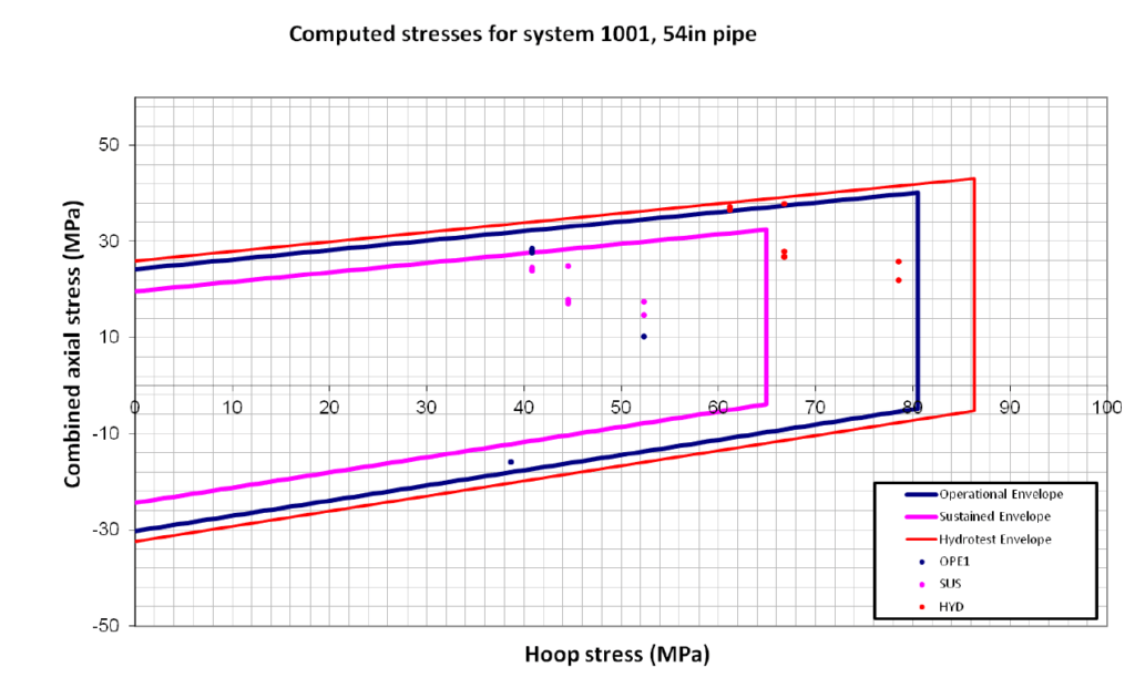
The stresses computed at each node were extracted and assessed with in-house software. The software plots the highest stresses as points against the allowable stress envelope for each load case. Points within the envelope indicate that the system is not overstressed with respect to the defined envelopes.
The long-term envelopes follow the guidelines of ISO 14692. They are multiplied by the part factors prescribed by the code: 0.89 for hydrotest, 0.83 for operation and 0.67 for sustained loading. The material data include a long-term axial tensile strength at 0:1 ratio of 29.19 MPa and a qualified strength of 97.0 MPa.
The model of system 1002 was split into SRU and GTU submodels. In both systems, the two outermost SRU trains were modelled in full. The other two SRU trains are identical to these and were included only for a small part close to the header. The conclusions for the modelled trains apply to them as well.
Continuation piping was included only to model its loads and boundary conditions on the analysed piping, and it was not stress checked. This piping comprised:
- one 54-inch underground GRP line per system
- above-ground steel piping to the D71X specification
- DN50 piping in system 1001
An anchor was applied at each GRP flange connecting to the D71X steel piping.
Stress Intensity Factors and Envelope Adaptations
The bend stress intensity factor and two envelope changes draw on recent findings of the ISO 14692 committee that were not yet part of the current code release. They were used to compute pipe stresses more realistically.
The bend stress intensity factor was set to 1.5 instead of the program default of 2.3, because 1.5 is expected to be specified for all bends in the next issue of ISO 14692. Where an update was not required, the conservative value of 2.3 was used.
The tee stress intensity factor was kept at the default of 2.3. Where a stress problem was found, it was updated to the value computed with the formulas of the latest issue of ISO 14692.
The two envelope changes are:
- The compression part of the envelope was constructed using an axial compression strength of 1.25 times the axial tensile strength.
- Large-diameter pipe is usually wound at an angle close to 90 degrees, which increases its hoop strength relative to its axial strength. ISO 14692 assumes a 2:1 ratio of hoop to axial strength. For the 54-inch pipe at high pressures, the analysis took the higher hoop strength into account.
Neither envelope change complies with the then-current issue of ISO 14692. Both were made to limit the required number of modifications to the system.
System Modifications and Results
Five types of modification were recommended to reduce the computed stresses to within acceptable levels:
- Additional reinforcement laminate on piping and fittings, which aims to increase the stress-carrying pipe area. The total required structural thickness is marked on the isometrics.
- Wrapping in polystyrene or an equivalent flexible material, intended to allow free displacement of the wrapped pipe under pressure or thermal expansion. A thickness of at least 50 mm can be considered sufficient.
- Removal of all thrust blocks shown on the received isometrics. The analyses indicate that they are not required and might increase piping stress.
- Two drag anchors in the 54-inch piping, to guard a fitting against the thermal expansion of a long straight pipeline. The required frontal area is marked on the drawings.
- Three-way stops at the above-ground DN50 valves.
All results apply to the modified system and are valid only if the modifications are implemented.
For system 1001, a few points fall outside the envelope on the compression side, all at the inside of elbows. The production process normally makes the inside of an elbow much thicker than the nominal thickness. It can therefore reasonably be expected that the actual stress at these points is lower and within the allowable.