
Branch Failures in a Buried GRP Firewater Ring
The firewater system is made from glass-reinforced plastic (GRP) pipe and is mainly underground. The main is a ring with large-bore branch connections, and smaller-bore branch connections feed the hydrants and monitors above ground. In early operation the system suffered a number of failures. These were repaired and improvement measures were taken, after which the failure frequency was reduced.
In summer 2010 a new series of failures occurred. Most of these were in the branches connected to the main, and the number of failures in the main was negligible. To reduce the future failure probability in the branch connections, the client requested a stress review. The review took into account failure mechanisms resulting from internal pressure, temperature, soil loads, installation and construction settlement, and pipe flexibility.
Two Design Concepts and the Selection of Critical Sections
The system uses two design concepts. In parts of it, concrete thrust blocks eliminate the pressure thrust loads in the piping, and the pipes between the thrust blocks are joined by coupling joints that are not tensile resistant. In other parts, the pipes and joints are fully tensile resistant, and thrust blocks are avoided. The mechanical behaviour of the two types differs, so critical sections were selected from each type.
Because the branch connection geometries are similar, characteristic sections were selected and assumed to be representative of the total system. Nine critical sections were analysed. Section no. 6 was removed from the original selection because the correct interpretation of the drawing showed that it did not need analysis. The conclusions for an analysed section apply to every section with the same characteristics, and the typical hydrant connections occur at multiple positions in the system.
CAESAR II Modelling and ISO 14692 Allowable Stress Envelopes
Each section was modelled separately in the static stress analysis program CAESAR II, and its buried piping module generated the bilinear soil springs. No dedicated pipe specification was available, so inputs came from the final manufacturing dossier and a specification for underground GRP lines, with assumptions where data were missing. Because of these assumptions, the results are indicative but better than purely qualitative. Where the dossier listed several wall thicknesses for one diameter, the lowest was used, and typically 1 mm was subtracted to exclude the inside and outside liners. Elbow and tee structural thicknesses were assumed to be 1.5 and 2 times the corresponding straight pipe thickness.
Only short-term strengths were available. A total factor of 4.0 on short-term strength, the minimum value specified in AD Merkblatt N1, was split within ISO 14692 into a sustained-stress safety factor of 1.5 and a short-term to long-term ratio of 2.67. A regression gradient of 0.065 was used to derive the factors for load durations shorter than the 20-year design life. Two values of the stress intensification factor for elbows were used: 2.3, the value in the current version of ISO 14692, and 1.5, which the review described as more realistic and which does not conform to the current version. In the pull-out assessments, the thrust blocks under examination were modelled as rigid elements on soil springs so that their displacement could be computed.
Computed stresses were plotted against five allowable stress envelopes to give a measure of the sensitivity of the predictions. These were the 20-year operational envelope, which includes a safety factor of 1.2 on the long-term qualified stress, and qualified envelopes for 20 years, 5 years, 1 year and 1000 hours, with allowable stresses multiplied by 1.2, 1.313, 1.458 and 1.679 respectively. A node just outside the operational envelope but within the 20-year qualified envelope indicates a design that is inadequate according to ISO 14692 but will not necessarily fail. A node outside the 1000-hour envelope indicates a risk that the piping will fail shortly after operation commences.
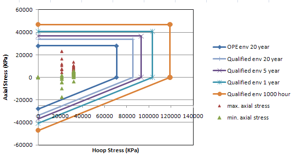
Coupling-Joint and Laminated-Joint Results Compared with Reported Failures
In the coupling-joint sections, the piping cannot accommodate the pressure thrust, so the thrust blocks must be adequately sized to prevent pull-out of the pipe from the coupling joints. The two valve sections were analysed for weight, the 16 barg design pressure and pressure thrust, without thermal effects. A typical maximum allowable displacement of a closing valve is 2 mm. On the assumption that the valve is bolted directly to the thrust block, blocks of 2000 x 2000 x 2000 mm for the DN250 valve and 1500 x 1500 x 1500 mm for the DN200 valve gave valve displacements in line with good practice. Below 1300 x 1300 x 1300 mm and 1000 x 1000 x 1000 mm respectively, the safety margin against pull-out becomes small. According to the client, a field check after the preliminary issue of the review found that the installed thrust blocks exceed the minimum required dimensions.
In the DN200 header with two 90-degree and two 45-degree bends, the thrust blocks of the 90-degree bends are interconnected and those of the 45-degree bends are separate. Under design conditions, the maximum displacement of each separate block was 1.2 mm and its rotation was less than 0.05 degrees, within good practice.
In the section with a DN450 header and a DN450 branch, both with coupling joints, a settlement of 3 mm was applied to the four thrust blocks in five combinations, and the stresses were up to 39.1% of the allowable. The piping was not more sensitive to differential settlement of the two closely spaced thrust blocks than to equal settlement of both.
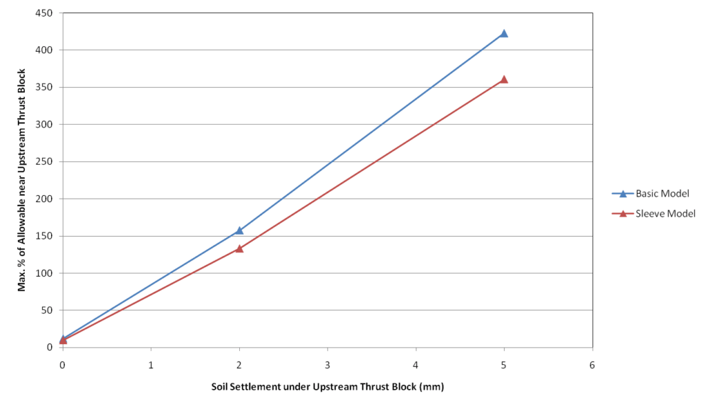
In the short DN100 branch with laminated joints, the highest compressive axial stress in the elbow below the hydrant was 82% of the allowable without settlement, a result of lateral deflection near the elbow due to thermal expansion. A settlement of 2 mm applied to both the upstream thrust block and the concrete hydrant foundation raised the maximum stress in the elbow to 114% of the allowable and the maximum stress next to the upstream thrust block from 12% to 168% of the allowable. Two models of the pipe within the upstream thrust block were analysed. In the basic model the pipe inside the block was modelled as a rigid element anchored at both ends. In the sleeve model the last 100 mm of that pipe was modelled without soil restraints to represent a rubber sleeve. In both models the maximum stress near the thrust block exceeded the allowable at 2 mm and 5 mm of thrust block settlement.
In the long DN100 branch with three elbows, the elbow stresses for the base soil parameters were 120% to 130% of the allowable in the 20-year operational envelope. Reducing the overburden compaction multiplier from 8 to 6.4 raised them to 134% to 147%, and reducing the yield displacement factor from 0.015 to 0.005 lowered them to 56% to 60%. Increasing the elbow thickness from 3.75 mm to 10 mm lowered them to 91% to 117% and moved the location of the high stress from the elbow to the adjacent sections. Using a stress intensification factor of 1.5 instead of 2.3 placed all stresses of the base case within the allowable long-term operational envelope.
In typical hydrant connection 3, which has a buried horizontal run of a little over 100 m, the maximum elbow stress with a stress intensification factor of 2.3 was 126% of the allowable in the 20-year operational envelope for a DN100 branch and 168% for a DN150 branch. With a stress intensification factor of 1.5, the maximum elbow stress in the worst case, the DN150 branch, was 116% of the maximum allowable operating stress and about 95% of the long-term qualified stress. The review stated that immediate failure is not expected for these elbows and that soil improvement is necessary for this connection.
The client reported five failures caused by overstress due to thrust block settlement. Thrust block settlement as a cause of failures also follows from the analysis.
Remedial Measures and Extent of Intervention
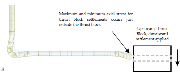
In the short DN100 branch, the maximum and minimum axial stresses from thrust block settlement occur just outside the thrust block. The settlement of an existing thrust block cannot practically be undone, but its adverse effect can be reduced by allowing the pipe to settle with the block, which smooths the differential settlement over a larger length of pipe.
The pipe next to the thrust block is exposed over the length of a number of pipe diameters, and the bedding under it is removed temporarily so that the pipe can adjust its curvature. The section is then backfilled, with or without flexible material applied next to the thrust block. The review described this measure for use if on-site observations show that thrust block settlement poses a problem. Increasing the pipe strength with additional laminations is also an option, but it is more complicated and often only temporary.
Where the pipe is purely encased in concrete and loaded by internal pressure, the discontinuity of hoop strain at the concrete-air interface introduces match-up axial wall bending stresses, which possibly create local circumferential pipe cracks. The remedial action is to introduce flexible material between the pipe and the concrete over the last encased section, typically one diameter, which smooths the discontinuity. For a DN100 pipe in a concrete hydrant foundation, a jacket pipe inside the foundation or a rubber sleeve near the ends of the foundation can reduce the stress concentrations.
The review assumed that most thrust block settlement occurs soon after installation. The client reported that no failure due to improper design has occurred since the last field intervention, and that the two failures since then were ascribed to external damage during installation or handling. On this basis, a large-scale preventive intervention was not deemed necessary.
Frequently Asked Questions
How are allowable stress envelopes set for GRP pipe when only short-term strength data exist?
A total factor of 4.0 on short-term strength, the minimum value in AD Merkblatt N1, was split within ISO 14692 into a sustained-stress safety factor of 1.5 and a short-term to long-term ratio of 2.67. A regression gradient of 0.065 then gave the factors for load durations shorter than the 20-year design life. Stresses were plotted against the 20-year operational envelope and qualified envelopes for 20 years, 5 years, 1 year and 1000 hours.
How much does thrust block settlement raise stress in a GRP branch with laminated joints?
In a short DN100 branch, a settlement of 2 mm applied to both the upstream thrust block and the concrete hydrant foundation raised the maximum stress in the elbow below the hydrant from 82% to 114% of the allowable. Next to the upstream thrust block, the maximum stress rose from 12% to 168% of the allowable.
How can stress from thrust block settlement be reduced in buried GRP piping?
Allowing the pipe to settle with the block smooths the differential settlement over a larger length of pipe. The pipe next to the thrust block is exposed over a number of pipe diameters, the bedding is removed temporarily, and the section is backfilled with or without flexible material next to the block. The review described this measure for use if on-site observations show that thrust block settlement poses a problem.