
Elbows replaced after hydrotest problems
A 5-inch glass-reinforced epoxy (GRE) transportation line runs buried between two locations. It connects to above-ground steel piping at both ends and to a steel manifold at about halfway. In total there are four connections between GRE and steel. The line is designed for 150 barg at 40°C and has a hydrostatic test pressure of 214 barg.
The line was originally built with large-radius elbows at every change of direction. Problems were experienced with these elbows during hydrotest, so they were replaced by tailor-made large-radius bends assembled from 22.5° elbows. The new bends were modelled with a structural wall thickness of 40 mm, against 12.9 mm for the straight pipe.
The task was to verify that the GRE piping with the new bends complies with ISO 14692.
How the buried line was modelled
The line was modelled in CAESAR II. Because the pipe is buried, the soil was represented as springs along its length, with stiffness values calculated for sand and a cover depth of 1.2 m above the pipe. The stresses in the GRE depend on how the connecting steel piping is routed and supported, so portions of that steel piping were included in the model.
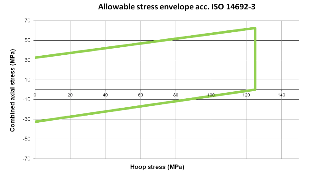
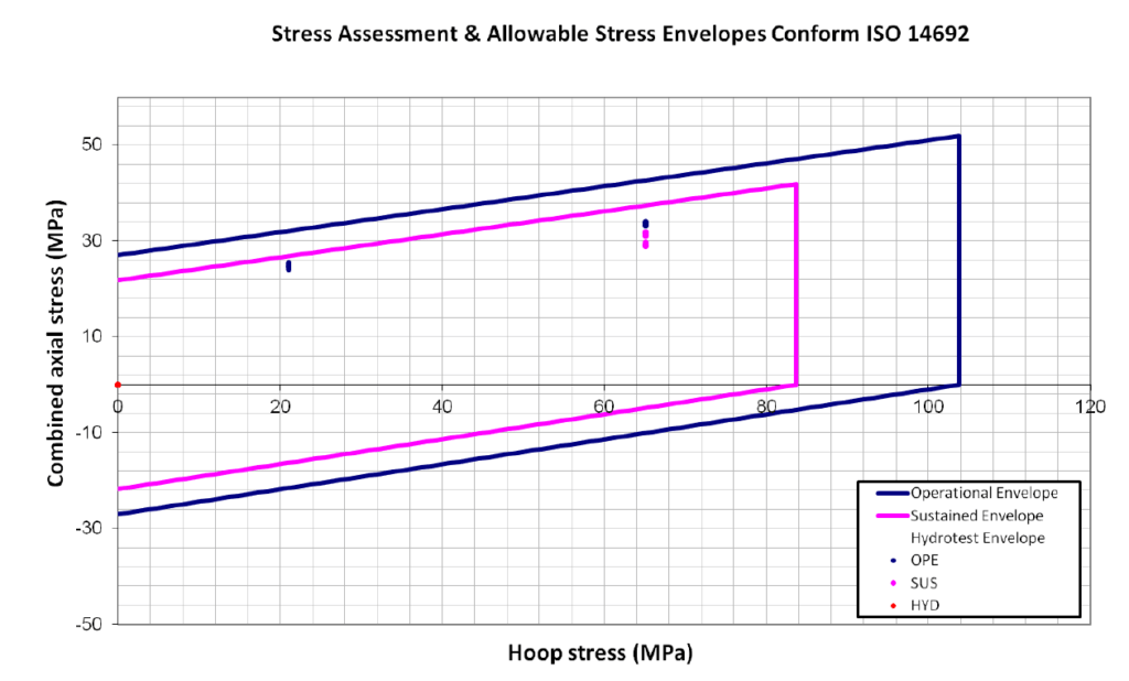
Three load cases were analysed: operational (weight, design pressure and temperature), sustained (weight and design pressure) and hydrotest (weight and 214 barg). Computed stresses were compared against the ISO 14692 allowable envelope, which combines hoop and axial stress. The safety factors depend on the load type: 1.5 for sustained loads, 1.20 for sustained plus secondary loads and 1.12 for occasional loads.
A minimum stress intensity factor of 1.5 was applied at the bends, in line with the value expected in the upcoming issue of ISO 14692. At some elbow nodes created during the burying step, CAESAR II applied its default value of 2.3 instead. As this is higher than 1.5, the validity of the calculations is not compromised.
Results
For design conditions, all stresses in the GRE piping are within the ISO 14692 allowables. The highest operational and sustained stresses lie within their respective envelopes, and no modifications to the piping system were required. Because of the high thickness of the new bends relative to the straight pipe, the highest stresses were found in the straight pipe, so the choice of stress intensity factor at the bends did not affect the conclusions.
The hydrotest was assessed in a separate, earlier analysis because the geometry differs during testing. With the elbows and adjacent straight pipe unburied, there is less resistance against the displacements imposed by the extension of the straight legs under pressure and temperature. That analysis shows the maximum displacements the bends can accommodate without exceeding the allowable stress envelope for pressure test conditions, and specifies a procedure to keep the hydrotest stresses within the allowable values. The loads on the steel flange pairs at the four GRE-to-steel connections were also reported.
Lessons from the analysis
Because the assembled bends are thicker than the straight pipe, the highest stresses were found in the straight pipe rather than at the bends. The difference between buried service and exposed test geometry meant the hydrotest needed its own assessment. Including the connecting steel piping in the model reflected the dependence of the GRE stresses on its routing and supports.