
A CAESAR II static stress analysis of a buried GRE firewater network against ISO 14692 found 18 bends and 10 tees overstressed in the original design. In the modified models, all stress points are within the ISO 14692 envelopes for the sustained, operational and hydro load cases, provided the system is built according to the recommendations.
Overstressed Elbows and Tees in a Buried GRE Firewater Network
The firewater system of a station consists of 80, 100, 150 and 200 mm inner diameter pipes in glass-fibre reinforced epoxy (GRE), designation Wavistrong EST 20. Most of the piping is buried and includes several connections to above-ground piping at hydrants and delivery lines.
The network has a header and 47 branches. The vertical pipes of the branches connect by flange to fire hydrants with and without monitor, hose reels (including the foam type), foam skid hydrants and fire breaching inlets. Two delivery pipes leave the discharge manifold, and three blind flanges are for connection to future water treatment plants. The design conditions are an operating pressure of 10 barg, a design pressure of 16 barg, a hydrostatic pressure of 24 barg and a design temperature of 65 °C.
The original design included a buried thrust block at the branches to the hydrants and delivery lines. Assessed against ISO 14692 at 16 barg and 65 °C, the original configuration was overstressed at 18 bends and 10 tees. In the North model, a fitting is counted as overstressed when its stress exceeds 90 % of the allowable values. The highest stress level was 173 %, at a 200×200 tee in the North model in the operational load case. Modifications to the original design were necessary.
CAESAR II Model, Load Cases, Allowable Stresses and Flange Check
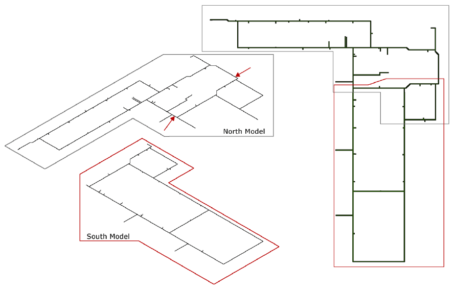
The static analysis used CAESAR II to compute deformations, loads and stresses. The model was split into a North model and a South model. The North model was analysed first, and the displacements determined at the boundary between the two were used as boundary conditions for the South model. Continuation piping included for overlap is not stress checked. The isometric drawings contained length inconsistencies from 1 mm to 3800 mm, and the longer length was used as the conservative option. Wind and seismic loads were not in scope.
Eleven load cases were analysed: one hydro case (weight of the water-filled pipe plus hydro pressure), eight operational cases and two sustained cases. The operational cases combine four temperatures (65, 60, 55 and 50 °C) with pressures of 10 barg and 16 barg. The sustained cases are weight plus 10 barg and weight plus 16 barg. For the South model, the displacements at the boundary are applied as D1 in the operational and sustained cases. The most critical load case appears to be the operational case at 65 °C and 16 barg, and the recommendations are based on it.
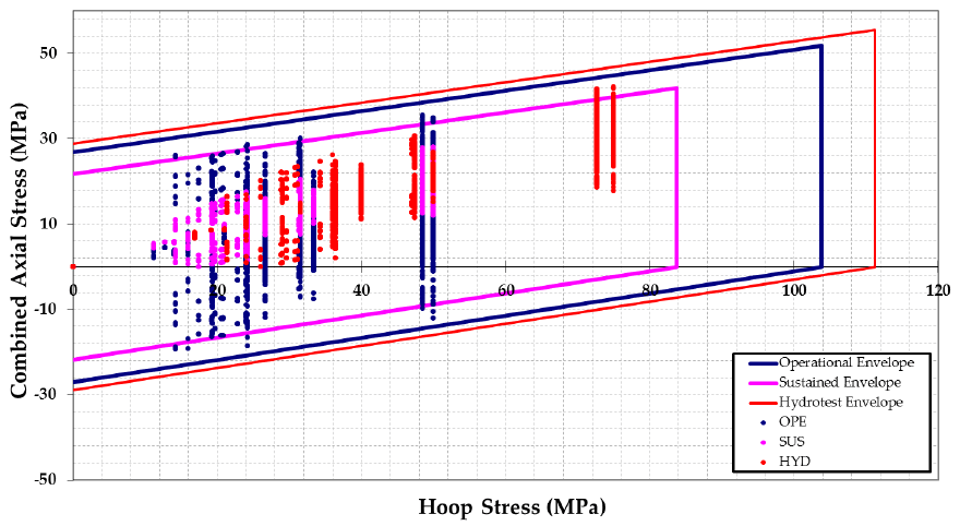
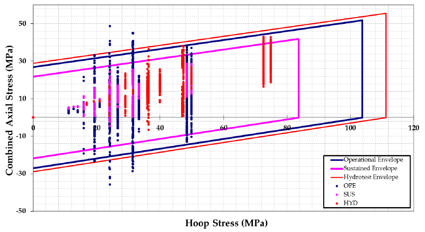
The CAESAR II stresses at each node were extracted and compared with the ISO 14692 allowable stresses in in-house software, which plots the highest stresses together with stress envelopes. A stress point inside the corresponding envelope indicates no overstressing. The envelope parameters were taken from the pipe supplier and are the same for all pipe diameters and thicknesses. The subscripts are A axial, H hoop, S short term and qs qualified stress.
ISO 14692 stress envelope parameters, all pipe diameters and EST 20 fittings
Parameter | Value |
SHS(2:1) | 250 MPa |
SAS(0:1) | 65 MPa |
σqs | 125 MPa |
SAL(0:1) | 32.5 MPa |
The loads on the GRE flanges were checked with the equivalent pressure rule. With a pipe supplier safety factor of 0.83, the qualified pressure for the operational case is 33.2 barg. All loads on the GRE flanges attached to the above-ground hydrant piping are well below this value.
Anchors, K-flex and Wall Thickness at Elbows and Tees
The buried thrust block at the branches to the hydrants and delivery lines should be removed. The hydrant and delivery lines should be anchored to the concrete slab: the anchor must be connected to the steel part of the hydrant and bolted to the slab. The connection should be sufficiently stiff to transfer the static and dynamic loads due to hydrant operation, and the displacements at the anchor should be zero. For the connecting pipe beyond the present scope, zero displacement at the GRE flange is advised.
The recommendation tables list 18 bends and 10 tees. Eight elbows and all ten tees receive K-flex of 50 mm thickness, 18 fittings in total. At 12 of these 18, the entry is 1 m of K-flex on both sides of the fitting. The other six entries are individual: two tees at the delivery pipes take 1 m on either side and between the two delivery pipes; one tee takes 1 m on the left and 2 m on the right, with the pipe length between nodes 16070 and 16040 increased by 2000 mm; one tee takes 1 m on the right and 1.5 m on the left up to the reducer; one elbow takes K-flex on the branch; and one elbow takes K-flex up to the sleeve on the left and 1 m on the right. K-flex is preferred over polystyrene provided that its elastic modulus is lower than 0.05 MPa.
Ten elbows have an increased wall thickness, with values from 4.5 to 8.3 mm. In agreement with the pipe supplier, the number of pipe reinforcements was minimised by applying K-flex.
Highest GRE Stress Levels Before and After Modification
Operational stress levels below are for 65 °C and 16 barg. In the North model, the highest operational stress level fell from 173 % at node 16070 to 90 % at node 13460, and the highest hydro stress level fell from 97 % at node 16070 to 91 % at node 15740. In the South model, the highest operational stress level fell from 140 % at node 13060 to 84 % at node 14020, and the highest hydro stress level fell from 89 % at nodes 13060 and 13420 to 86 % at node 13020.
Highest stress level per model and load case
Model | Load case | Original | After modification |
North | Operational | 173 % (node 16070) | 90 % (node 13460) |
North | Hydro | 97 % (node 16070) | 91 % (node 15740) |
South | Operational | 140 % (node 13060) | 84 % (node 14020) |
South | Hydro | 89 % (nodes 13060, 13420) | 86 % (node 13020) |
In the North model, the sustained case was already within the original envelope. After modification, all stress points are within the ISO 14692 stress envelopes for the sustained, operational and hydro load cases. With the thrust block removed and the anchor between hydrant and concrete slab in place, the flange loads are within limits. Provided that the system is built according to the recommendations, the firewater system fulfils the ISO 14692 requirements for sustained, operational and hydrotest conditions.
Original Overstress and Future Steel Connections at Blind Flanges
In the original North and South models, the operational load case is critical: the five highest operational stress levels were 144 to 173 % in the North model and 112 to 140 % in the South model. Piping of the future water treatment plants may be designed in steel. The three blind flanges to these plants are modelled as an anchor, which gives maximum displacement at the tee connecting the branch and the header. Extra attention is advised when future connections are designed, and the displacements at the blind flanges should be close to zero.
Buried GRE Piping Stress Analysis Frequently Asked Questions
Which load case is critical for buried GRE firewater piping under ISO 14692?
The most critical load case appears to be the operational case at 65 °C and 16 barg, and the recommendations are based on it. In the original models, the five highest operational stress levels were 144 to 173 % in the North model and 112 to 140 % in the South model.
When is K-flex preferred over polystyrene at GRE elbows and tees?
K-flex is preferred over polystyrene provided that its elastic modulus is lower than 0.05 MPa. K-flex of 50 mm thickness is recommended at 18 fittings: eight elbows and ten tees.
How are blind flanges modelled for future connections to buried GRE piping?
The three blind flanges are modelled as an anchor, which gives maximum displacement at the tee connecting the branch and the header. Piping of the future water treatment plants may be designed in steel, and the displacements at the blind flanges should be close to zero when future connections are designed.