
Static stress analysis of two buried GRE firewater subsystems in CAESAR II covered three load cases with a design pressure of 13.4 barg and a maximum design temperature of 40 °C. The stress analysis report, a preliminary issue, records wall thickness increases and polystyrene on five isometrics and concludes that, once these are implemented, static pipe stresses are acceptable and GRE flange loads are moderate.
The firewater system upgrade at a main degassing station includes buried glass-reinforced epoxy (GRE) piping with a winding angle of 55 degrees. The system has two subsystems: a firewater distribution network and a deluge system for the tanker unloading bay. The two subsystems were modelled and analysed in CAESAR II, one model each. The GRE connects to steel piping whose configuration was unknown. The static stress analysis assessed the standard arrangement of both subsystems to ISO 14692.
GRE Material Data and ISO 14692 Stress Assessment
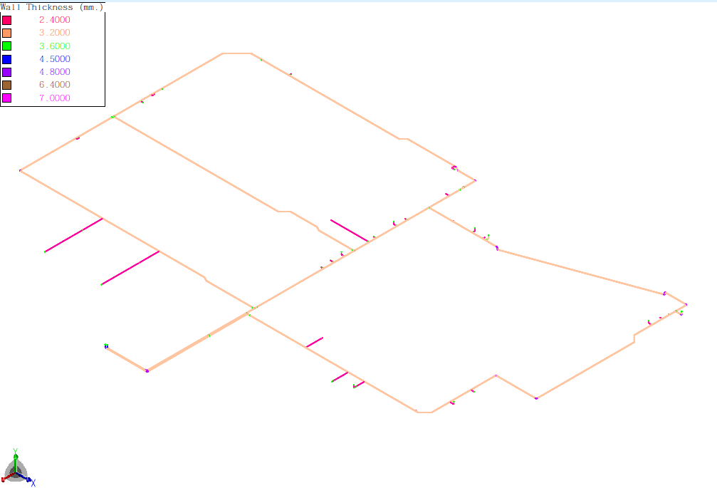
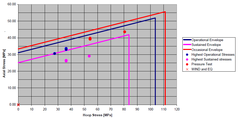
The pipe material properties and the allowable stresses are based on material data provided by the pipe manufacturer. The GRE has an axial elastic modulus of 12,000 MPa, a hoop elastic modulus of 20,500 MPa and a shear modulus of 11,500 MPa. The Poisson ratio is 0.38 for hoop load (νhoop/axial) and 0.65 for axial load (νaxial/hoop). The thermal expansion coefficient is 20 × 10⁻⁶ mm/mm/°C and the specific gravity is 1.85. The structural wall thickness is 2.4 mm on ND100 (EST 25), 2.4 mm on ND150 (EST 20) and 3.2 mm on ND250 (EST 16). The stress assessment was performed to the allowable load-case-dependent stress envelope. The GRE pipe stress was assessed to ISO 14692 using the manufacturer’s material data, and the detailed assessment is recorded in an ISO stress check for each model.
Design Conditions, Load Cases and Cover Depth
The design pressure is 13.4 barg, the maximum design temperature is 40 °C and the installation temperature is 21 °C. These values differ from those shown on the isometrics and were confirmed by another party.
Three load cases were analysed, each including the weight of the water-filled pipe. The hydro test is at 20.1 barg and 21 °C (weight plus test pressure). The operational case is at 13.4 barg and 40 °C (weight, maximum design temperature and design pressure). The sustained case is at 13.4 barg and 21 °C (weight and design pressure). The pipe content is water at a density of 1,000 kg/m³.
The cover depth was taken from the isometrics. No general arrangement drawing showing the ground elevation was available, and the burial depth was estimated from near hydrant locations. In the distribution network model the cover depth is approximately 950 mm, measured from the top of the pipe. The deluge system model uses three cover depths: 950, 1,420 and 2,000 mm.
Anchored and Unrestrained Cases at Steel Connections
Where the connecting piping was unknown, two situations were analysed. In the first, an anchor was introduced at the connection and the restraint loads were established; they are listed in the restraint summary of the model output. In the second, the connection was unrestrained and the displacements of the free end were established. These displacements are shown on the stress isometrics as displacements to be accommodated. The worst case was used to assess the stresses.
Wall Thickness and Polystyrene Adjustments, Stresses and Flange Loads
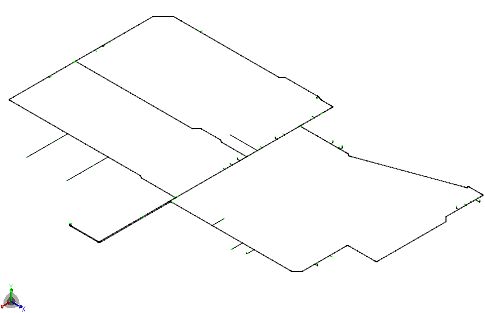
Adjustments to the standard arrangement are required on five isometrics to bring stresses within allowable limits. In the distribution network model, wall thickness increases apply to two isometrics and polystyrene at a wall penetration applies to a third. In the deluge system model, polystyrene around a tee branch applies to two isometrics, and one of these also has a wall thickness increase. In total this is three wall thickness increases and three polystyrene adjustments.
Where the wall thickness was increased, the effective thickness TE is indicated on the isometrics, and the model plots show the applied thicknesses TE by colour. The exact dimensions used are in the model input. The analysis concludes that, once these adjustments are implemented, static pipe stresses are acceptable and the GRE flange loads are moderate. The flange loads are given in the restraint summary of the model output. These conclusions are from the preliminary issue of the stress analysis report.
Displacement Requirement at Steel Connections
The steel piping must not impose displacements at the connection with the GRE piping in excess of the established free-end displacements. The stress analysis report emphasises this requirement.
Frequently Asked Questions
Which load cases are used to analyse buried GRE firewater piping in CAESAR II?
Hydro test, operational and sustained. Design Conditions, Load Cases and Cover Depth.
How do you analyse a GRE connection to steel piping of unknown stiffness?
An anchored case and an unrestrained case, with the worst case used to assess the stresses. Anchored and Unrestrained Cases at Steel Connections.
What adjustments bring GRE firewater piping stresses within allowable limits?
Wall thickness increases and polystyrene on five isometrics. Wall Thickness and Polystyrene Adjustments, Stresses and Flange Loads.