
A buried GRE fire water ring was assessed in CAESAR II against the ISO 14692 allowable stress envelope. Static stresses stayed within the envelope for all load cases after additional lamination at nine bends, and the settlement analysis set a 4 MPa axial margin on the operational or occasional envelope.
ISO 14692 Assessment Scope for a Buried GRE Fire Water Ring
A buried fire water ring made from reinforced fibreglass (GRE) pipe was analysed. The system is Class A according to the Service Limit State (SLS), and its stresses were assessed according to ISO 14692. The design pressure was 16 barg, the test pressure 24 barg, and the design temperature range -5 °C to 40 °C, with an installation temperature of 25 °C. Pipe sizes ranged from DN 25 to DN 350.
The laminate has a 55° winding angle, an axial elasticity modulus of 12,000 MPa and a circumferential modulus of 20,500 MPa. For GRE the allowable stress levels in the hoop and axial directions differ, and the allowable axial stress depends on the stress acting in the circumferential direction. The system is buried, and the analysis focused on the axial stress caused by restraint from the soil. The effect of differential settlement from earthquake was analysed in a separate model.
A waterhammer analysis was outside the scope. The system is buried, so unbalanced loads from pressure surges do not result in large-scale pipe displacements. Dynaflow experience is that transient pressure remains within 1.4 times the rated pressure (22.4 barg) if hydrant and deluge valve closure times are not faster than five seconds.
CAESAR II Model and ISO 14692 Assessment of Buried GRE Pipe
The pipe stress model was built in CAESAR II. The FRP material module represented the different axial and hoop properties of the laminate, including Poisson ratios of 0.38 (hoop/tensile) and 0.65 (axial/hoop). The model was buried using the CAESAR II buried pipe modeler, with typical soil values that Dynaflow has used on projects in similar areas: a friction coefficient of 0.5, an internal friction angle of 30° and a soil density of 1,900 kg/m³. The modeler assumes that the weight loads of pipe and content are balanced by the soil reaction, so all weights in the buried sections are zero.
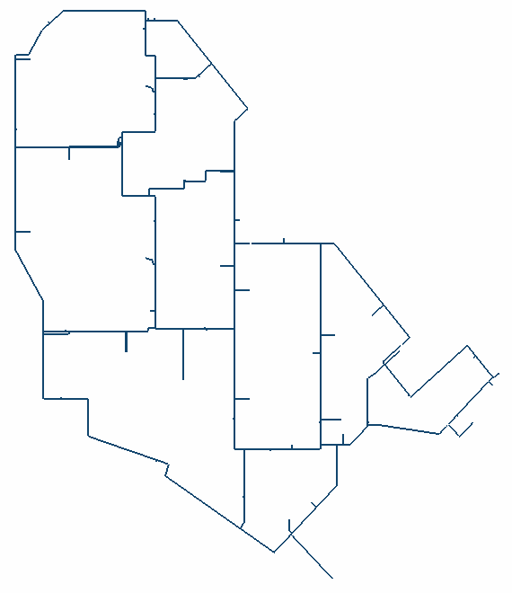
Stress intensification factors at fittings were applied in accordance with ASME B31.3, and shear and axial stresses were combined into a code stress for evaluation purposes. An indicative allowable of 43 MPa at 40 °C was used during the iterative design process. Because the allowable axial stress depends on the circumferential stress, the assessment cannot be limited to comparing the code stress with an allowable, and the code stress is only an indicative figure.
The stresses were evaluated according to the method in ISO 14692, using an allowable stress envelope generated from manufacturer data: an LCL of 130 MPa at 65 °C, Sas(0:1) of 75 MPa and Shs(2:1) of 210 MPa. The part factors f2 were 0.83 for the operating case (pressure and thermal), 0.67 for the sustained case (pressure) and 0.89 for the occasional case (hydrotest). The final assessment plotted axial and hoop stress for the five highest loaded nodes in the allowable stress envelopes.
Part factor f2 by case
Case | f2 |
Operating (pressure and thermal) | 0.83 |
Sustained (pressure) | 0.67 |
Occasional (hydrotest) | 0.89 |
Five static load cases were analysed: three operating cases at 16 barg with temperatures of 40 °C, -0.6 °C and -5 °C, and two sustained cases at 16 barg and 24 barg (test pressure).
Static load cases
Case type | Pressure (barg) | Temperature (°C) |
Operating | 16 | 40 |
Operating | 16 | -0.6 |
Operating | 16 | -5 |
Sustained | 16 | not stated |
Sustained | 24 (test pressure) | not stated |
GRE Bends, Tees and Rubber Seal Lock Joints
Modifications introduced during the iterative analysis were limited to wall thickness increments at some bends. GRE bends usually have 1.5 times the wall thickness of regular pipe. At the usual bend wall thickness the stresses at nine bends exceeded the allowable, and additional lamination is required at these bends: three of DN 350, three of DN 200 and three of DN 150. The additional lamination is 2.2 mm at DN 350 (total wall thickness 8.8 mm), 1.25 mm at DN 200 (total 5.0 mm) and 1.2 mm at DN 150 (total 4.8 mm). These changes are incorporated in the results.
Bends with additional lamination
Size | Bends | Additional lamination (mm) | Total wall thickness (mm) |
DN 350 | 3 | 2.2 | 8.8 |
DN 200 | 3 | 1.25 | 5.0 |
DN 150 | 3 | 1.2 | 4.8 |
The stress levels in the line are dominated by stress intensification at the intersections. The intensification factors used are based on successful projects and limited to 2.3. The total wall thickness of GRE tees is always twice that of plain pipe, and this proved sufficient for all tees in the system, so no additional lamination was required.
The joints in the ring are Rubber Seal Lock Joints. These mechanical joints have play that allows deflection during installation and simplifies installation.
Earthquake Settlement Analysis of Buried GRE Pipe
The effect of settlement was analysed in a separate model. A shear fault with an infinitely short wavelength crossing the pipe would shear it off. If the shear wave generates differential displacements with a finite wavelength, the flexibility of the pipe is sufficient to accommodate the imposed displacement field. The model imposed a displacement wave with an amplitude of 40 mm at wavelengths of 10 m and 20 m. A temperature of 50 °C was included as a separate case for conservatism. The case of -0.6 °C is not a defining case and was not considered. The highest stress resulting from the forced pipe bending was 4 MPa.
In the static stress analysis for the operational case, a margin of 4 MPa in the axial direction must therefore be maintained with respect to the operational envelope if the settlement is of a sustained nature. If the settlement results from an earthquake and the earthquake load is considered occasional, the 4 MPa margin applies with respect to the occasional envelope.
Static and Settlement Results for Buried GRE Pipe
The static stresses for all load cases considered were within the allowable envelope. With the results of the settlement analysis applied, the allowable envelope is shifted by 4 MPa.
Frequently asked questions on GRE piping
Why can a code stress check not be used to qualify GRE pipe?
The allowable axial stress depends on the circumferential stress, so the assessment cannot be limited to comparing the code stress with an allowable. The code stress is only an indicative figure, and the final assessment plots axial and hoop stress in the ISO 14692 allowable stress envelopes.
How is earthquake settlement assessed for buried GRE pipe?
The effect of settlement was analysed in a separate model with a displacement wave of 40 mm amplitude at wavelengths of 10 m and 20 m. The highest stress from the forced pipe bending was 4 MPa, so a 4 MPa axial margin must be maintained with respect to the operational envelope if the settlement is sustained, or the occasional envelope if the settlement results from an earthquake.
Do GRE tees and bends need extra wall thickness?
Nine bends needed additional lamination: three of DN 350, three of DN 200 and three of DN 150. No tee needed it, because the total wall thickness of GRE tees is always twice that of plain pipe and this proved sufficient for all tees in the system.