
A CAESAR II stress analysis of a revised high-pressure blowdown line operating at 20.6 barg and 160 °C found that the system as proposed did not meet ASME B31.3 because of large thermal displacements of the DN600 header. If guide support S1 is replaced by a restraint in the z-direction only, the stresses meet the code, with a highest code stress of 68% of the maximum allowable stress in the hot expansion case.
New Vessel Connection to a High-Pressure Blowdown Line
A client planned to connect an additional vessel to its existing high-pressure blowdown line. The additional vessel is to be placed near an existing vessel and connected through new routing and an extension of an existing connection. The connection to the additional vessel will be made later, so the connections at the vessel are temporarily closed with blind flanges. The revised line is to be built in the short term.
The line operates at 20.6 barg and 160 °C and carries cyclohexane. The cold case is -10 °C at the same pressure, and the hydrotest pressure is 37.5 barg. The objective was a static stress analysis of the revised line. The analysis considered the stresses in the piping and the loads on the line components (valves and flanges), and set out recommendations for changes where needed so that the system meets the requirements for static loading.
DN600 Header Displacements Imposed From the Earlier Model
The revised section connects to the rest of the system at the DN600 header. The system before the revision had been analysed in CAESAR II in an earlier project, and the new model was fitted into the existing earlier models of the line. Displacements of the DN600 header were read from the earlier model per load case and imposed on both sides of the 24-inch by 12-inch tee on the header. The hydrotest, hot operating and cold operating cases each used the displacements for the corresponding condition of the earlier model. The displacements are labelled D1 for the hot operating condition, D2 for the cold operating condition and D3 for the hydrotest condition.
CAESAR II Model Inputs, FE/Pipe SIFs and Load Cases
The line was modelled in CAESAR II from the ISO drawings and component data supplied by the client, with blind flanges on the connections, as in the provisionally planned situation. The material is EN 1.4571, in material group EN 15E0. The ‘austenitic steel’ entry of the CAESAR II material database was selected as an equivalent material. The allowable stresses entered, 146 MPa for the cold condition and 135 MPa at 160 °C, are based on values used by the client and replace the database values. Stresses were checked against ASME B31.3 with these allowable stresses.
The analysis used a cyclohexane density of 779 kg/m³ and insulation with a density of 80 kg/m³ and a thickness of 80 mm. Valve masses supplied by the client are 150 kg for a PN40 DN150 ball valve with actuator, 90 kg for a PN40 DN150 ball valve with handwheel and 20 kg for a PN40 DN50 ball valve with handwheel. The branch of the 24-inch by 12-inch tee has a wall thickness of 12.5 mm.
To make the model more accurate, the two 6-inch by 2-inch tees were analysed in detail with the finite element program FE/Pipe. The analysis gave stress intensification factors (SIFs) for these tees, which were then entered in CAESAR II.
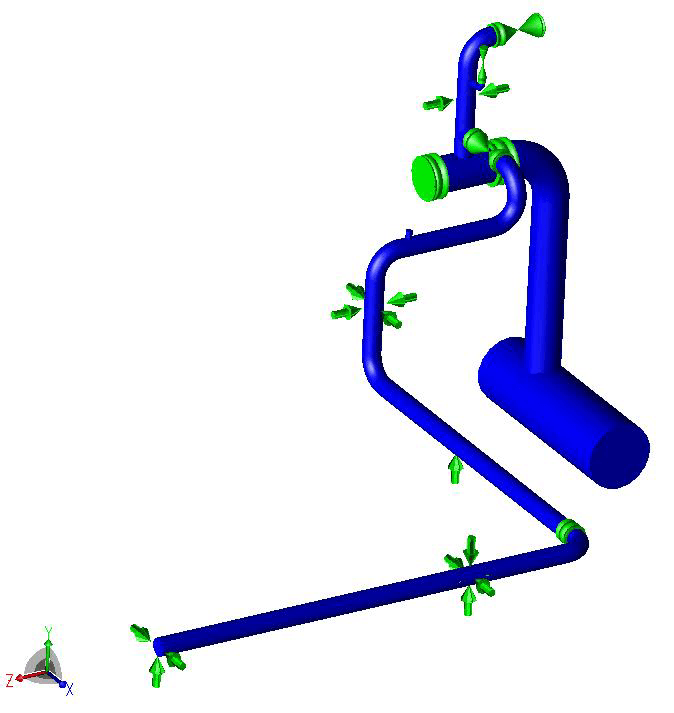
The model contains five supports: S1 at node 230, S2 at node 630, S3 at node 670, S4 at node 730 and S5 at node 750. S2 is modelled as a guide and S3 as +Y. S4 is modelled as a fixed point and S5 as +Y with a guide. The guide supports all have a gap of 2 mm. S1 is modelled as the z-direction restraint recommended below, with a 2 mm gap.
Nine open flanges are listed for the system: two DN300 PN25, five DN150 PN40 and two DN50 PN40. Where two flanges are directly coupled, only one is listed. Blind flanges are not listed because they are not subject to significant loads.
Six load cases were defined: HYD (hydrotest), OPE1 (hot operating), OPE2 (cold operating), SUS (sustained), EXP1 (hot expansion, OPE1 minus SUS) and EXP2 (cold expansion, OPE2 minus SUS). HYD combined the weight of the line and its water content, the hydrotest pressure and the imposed header displacements. OPE1 and OPE2 each combined the weight of the line and its cyclohexane content, the operating pressure, the thermal load at 160 °C or -10 °C respectively, and the imposed header displacements for that condition. SUS combined the weight of the line and its cyclohexane content with the operating pressure.
ASME B31.3 Exceedance and Recommended Change to Support S1
The analysis showed that the system as proposed by the client did not meet ASME B31.3. The exceedance was caused by the large thermal displacements of the DN600 header, which produced high stresses in some tees. The recommendation concerns support S1 on the upward DN150 line. In the proposed design, S1 was a guide, which restrains movement along the header axis (the x-direction) and perpendicular to it (the z-direction). The recommended modification replaces the guide with a restraint in the z-direction only. If this recommendation is adopted, the stresses in the system meet ASME B31.3. The results below are for the system with this change.
Stress and Flange Results With the Recommended S1 Change
With the recommended change, the system showed no exceedance of the ASME B31.3 stress code. For HYD, SUS, EXP1 and EXP2, the highest code stress is reported as a percentage of the maximum allowable stress applicable to that case. HYD reached 59% and SUS 65%, both at one node on a DN150 bend. EXP1 reached 68% and EXP2 14%, both at a different node, also on a DN150 bend. The highest value was 68%, in EXP1.
| Load case | Highest code stress, % of maximum allowable stress |
|---|---|
| HYD | 59 |
| SUS | 65 |
| EXP1 | 68 |
| EXP2 | 14 |
In the system with the recommended change, the flange forces in OPE1 and OPE2 were checked with the equivalent pressure method, without a Koves factor, and are within the permitted values. Pressure ratings were corrected for operating temperature in accordance with EN 1092-1:2007. The three valves in the line have the same pressure rating as their connecting flanges, so the loads on the valves are also within limits.
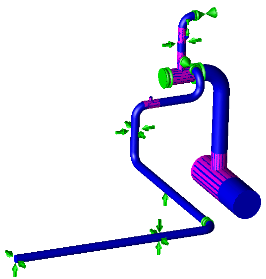
DN600 Header Displacement and the S1 Support Change
The header displacements used in the analysis were read from the model of the earlier project and imposed in the hydrotest and operating cases. In the system as proposed, the large thermal displacements of the DN600 header caused an exceedance of the ASME B31.3 stress code, with high stresses in some tees. One modification was recommended, to support S1, where a restraint in the z-direction only replaces the guide. If the change is adopted, the stresses meet ASME B31.3, the flange loads are within the permitted values and the line meets the requirements for static loading.
Blowdown Line Stress Analysis FAQ
How are existing header displacements included in a new branch stress analysis in CAESAR II?
Displacements of the DN600 header were read from the model of the earlier project per load case. They were imposed on both sides of the 24-inch by 12-inch tee on the header. The hydrotest, hot operating and cold operating cases each used the displacements for the corresponding condition of the earlier model.
Why did the proposed blowdown line not meet ASME B31.3?
The large thermal displacements of the DN600 header produced high stresses in some tees, which caused an exceedance of the ASME B31.3 stress code in the system as proposed.
What change to support S1 was recommended?
In the proposed design, S1 on the upward DN150 line was a guide, restraining movement along the header axis (x-direction) and perpendicular to it (z-direction). The recommendation replaces the guide with a restraint in the z-direction only. If the recommendation is adopted, the stresses in the system meet ASME B31.3.
How are stress intensification factors found for branch tees in CAESAR II?
The two 6-inch by 2-inch tees were analysed in detail with the finite element program FE/Pipe. The analysis gave stress intensification factors for these tees, which were then entered in CAESAR II.
How were the flange and valve loads checked?
The flange forces in OPE1 and OPE2 were checked with the equivalent pressure method, without a Koves factor, with pressure ratings corrected for operating temperature in accordance with EN 1092-1:2007. The three valves have the same pressure rating as their connecting flanges, so the loads on the valves are also within limits.