
An axisymmetric finite element analysis checked the flued flange expansion joint of a fixed-fixed tubesheet reboiler for low cycle fatigue, high cycle fatigue and primary stress to ASME Section VIII Division 2, at mean (26 mm) and minimum (22 mm) wall thickness. The largest low cycle fatigue stress range was 290 MPa against a 340 MPa allowable, the high cycle fatigue assessment passed at all locations for 7000 cycles, and the maximum primary membrane plus bending stress was 99.61 MPa against a 136 MPa limit.
Cyclic Secondary Stresses at a Flued Flange Expansion Joint
Reboiler and Assessment at a Glance
- Equipment: fixed-fixed tubesheet exchanger with an inner tube bundle and an outer shell body.
- Fluids: steam on the shell side, aqueous glycol on the tube side.
- Shell material: SA-240M 304.
- Expansion joint wall thickness: mean 26 mm and minimum 22 mm.
- Corrosion allowance: 0 mm.
- Recommended cycles: 7000.
- Code: ASME Section VIII Division 2.
- Scope: static design cases only.
Function of the Expansion Joint
A flued flange expansion joint in the shell accommodates thermal expansion and contraction of the shell relative to the tube bundle during operation.
Fatigue Concern
Temperature variations in the shell and tubes induce cyclic secondary stresses in the shell at the expansion joint, and the secondary loads are mainly the result of thermal expansion. Alternating stresses at regions of local stress concentration, such as welds and defects, may cause crack initiation and subsequent crack growth.
The expansion joint was assessed for low cycle fatigue, high cycle fatigue and primary stress to ASME Section VIII Division 2. The assessment used the recommended 7000 cycles, a default design value for most vessels that corresponds approximately to one cycle each day over a design life of twenty years.
Wall Thickness Cases
To examine wall thinning during forming of the shell, two wall thicknesses at the expansion joint were assessed for low and high cycle fatigue: the mean thickness of 26 mm and the minimum thickness of 22 mm. The shell is specified with a corrosion allowance of 0 mm, which implies that no separate analysis of corroded and uncorroded conditions is needed.
FE/Pipe Axisymmetric Model of the Expansion Joint
Model Setup
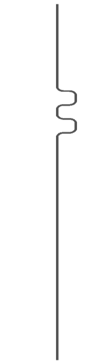
- Software and model type: FE/Pipe, two-dimensional axisymmetric model of the shell.
- Shell material: SA-240M 304.
- Material properties: taken from ASME Section II Part D where possible and averaged over the design temperature range of 14 to 250 °C.
- Construction guidance: recommendations for model construction are given in TEMA (9th Edition) Section 5.
Boundary Conditions
Three main boundary conditions were applied.
- Axial restraint: zero axial displacement at the top and bottom edges of the model, which simulates the flanges at both ends of the shell and allows radial displacement. It applies to all cases.
- Internal pressure: applied on the inside edge of the shell, with parameters adjusted for each case.
- Thermal boundary condition: applied on the inside edge of the shell, with parameters adjusted for each case.
Axial Thrust Stiffness Check
The axial thrust from internal pressure was not applied to the shell model, because the tube bundle restrains it with a counteracting axial load. A stiffness comparison verified this. The tube bundle stiffness is calculated as N·E·A/L.
- Number of tubes, N: 2635.
- Young’s modulus, E: 180 GPa.
- Cross-sectional area, A: 156 mm².
- Tube length, L: approximately 6000 mm.
- Tube bundle stiffness: 12,331,800 N/mm.
- Expansion joint spring rate (PV Elite) at the mean wall thickness of the shell and expansion joint: 357,410 N/mm.
- Expansion joint spring rate (PV Elite) at the mean wall thickness of the shell and the minimum wall thickness of the expansion joint: 219,370 N/mm.
At the mean wall thickness, the tube bundle is approximately 35 times stiffer than the shell body, and approximately 3 percent of the axial pressure thrust is transferred to the shell body.
Load Cases and ASME Code Checks
Six Static Load Cases
Six static load cases were analysed, expanded from the supplied cases to observe the highest potential stress cycling.
Case # | Cases Name | Delta T | Shell Side Pressure[MPa] |
|---|---|---|---|
1 | Idle(Ambient) | 0 | 0 |
2 | Start up (Winter) | -42 | 0 |
3 | Start up (Summer) | -20 | 0 |
4 | Start up (Winter) with Operating Pressure | -42 | 2.265 |
5 | Start up (Summer) with Operating Pressure | -20 | 2.265 |
6 | Design Limit | 27 | 2.265 |
The start-up cases with operating pressure examine the potential stresses during start-up and shell pressurisation. The design limit was selected in preference to the operating and steam failure cases because its temperature differential between shell and tubes is larger than in those cases, which implies a higher stress potential.
Stress States and Stress Ranges
The six cases give four stress states:
- Idle (ambient)
- Start-up (winter or summer)
- Start-up (winter or summer) with operating pressure
- Design limit
As a conservative approach, the maximum stress range was taken as the absolute sum of the two largest stress states, and the remaining two states give the second range. This gives two stress ranges for evaluation in the low and high cycle fatigue assessments. Stress ranges were tabulated at seventeen locations along the shell cross-section, labelled A to Q.
Low Cycle and High Cycle Fatigue Checks
- Low cycle fatigue: the primary stress ranges (PL+PB) are combined with the secondary stress range Q and compared with an allowable of 2·Sy,avg, where Sy,avg is the average of the yield stress in the cold and hot states.
- High cycle fatigue: at notches, which are regions of local stress concentration, the low cycle fatigue stress is extended with the peak stress contribution F. The allowable design cycles N1 and N2 come from the appropriate S-N fatigue curve and are assessed against the recommended 7000 cycles with the cumulative damage rule.
A weld surface strength-reduction factor of 1.22, based on the degree of non-destructive testing, was multiplied with the two stress ranges at the full penetration welds in the expansion joint, and a factor of 1 was used at all other surfaces. The two resulting stress amplitudes give N1 and N2 as specified in ASME Section VIII Division 2.
Primary Stress Check
- Failure modes investigated: plastic collapse and burst.
- Loads: design pressure only, with thermal effects excluded.
- Model: minimum wall thickness only, because it produces the largest stress in the wall membrane.
- Method: stress linearisation across the wall thickness in regions of high stress, giving the membrane and bending components.
- Limits: Pm<Sh and Pm+PB<1.5·Sh, where Sh is the hot allowable stress of 90.8 MPa. The membrane stress was treated as a global stress.
Fatigue and Primary Stress Results for the Expansion Joint
The shell body and expansion joint met the acceptance criteria in the low cycle fatigue, high cycle fatigue and primary stress assessments for the current design and loading conditions.
Low Cycle Fatigue
The largest low cycle fatigue stress range in the tabulated results was 290 MPa, against the 340 MPa allowable (2·Sy,avg), which is approximately 85 percent of the allowable.
High Cycle Fatigue
The high cycle fatigue assessment passed at all locations for the recommended 7000 cycles. Where the stress amplitude was below 94 MPa, generally amplitude 2 in the tabulated results, the allowable cycles N2 approach infinity and the criterion reduces to 7000/N1<1. The assessment showed that the reboiler can accommodate more than 100,000 cycles.
Primary Stress
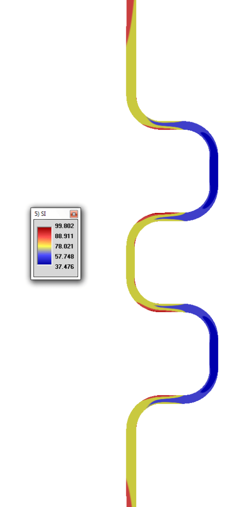
The highest stress regions, above 90 MPa, were in the expansion joint section at locations C, G, K and O, where stress concentration lines were created for linearisation. Of the four linearised locations, the maximum membrane stress was 70.82 MPa at location G, against the 90.8 MPa limit. The maximum membrane plus bending stress was 99.61 MPa, also at location G, against the 136 MPa limit. Both are within 78 percent of the allowable stress at the design limit temperature.
Stress Concentration Line Results
Location | Membrane Stress [MPa] | Bending[MPa] | Membrane + Bending[Mpa] |
|---|---|---|---|
SCL(C) | 68.34 | 55.6 | 94.98 |
SCL(G) | 70.82 | 58.42 | 99.61 |
SCL(K) | 70.59 | 58.42 | 99.17 |
SCL(O) | 68.97 | 54.99 | 95.75 |
Second Finite Element Package Check and Validity Limits
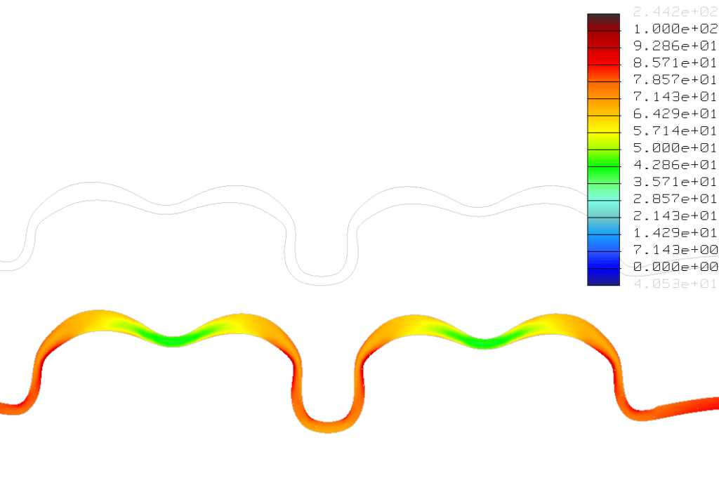
The primary stress results and the location of the maximum were confirmed with a second finite element package, Pro-Mechanica. The conclusions are not valid if large thermal differences between shell and tubes are expected. The conclusions apply to the current design and operating conditions, and a change to either requires reanalysis.
Frequently Asked Questions
How many cycles can a flued expansion joint in a fixed-tubesheet reboiler accommodate under ASME VIII Division 2?
The high cycle fatigue assessment passed at all locations for the recommended 7000 cycles and showed more than 100,000 cycles.
Can axial pressure thrust be left out of a finite element model of a reboiler shell with an expansion joint?
The tube bundle stiffness of 12,331,800 N/mm is approximately 35 times the 357,410 N/mm spring rate at mean wall thickness, so approximately 3 percent of the thrust reaches the shell body
How is a weld strength-reduction factor applied in a high cycle fatigue check?
A factor of 1.22 was multiplied with the two stress ranges at the full penetration welds in the expansion joint, and a factor of 1 was used at all other surfaces.