The API 618 DA3 study at the Q8 Terminal, commissioned by Wintershall Noordzee and executed by Dynaflow Research Group, was initiated to ensure the mechanical reliability and performance of the reciprocating compressor piping system. This study focuses on the evaluation of pulsation and vibration per API 618 (5th Edition, 2007) Design Approach 3 for the Ariel 3-stage reciprocating compressor serving the Q8 gas terminal.
The scope includes modelling, simulation, and assessment of the entire piping route from the slug catcher (V-5) to the discharge scrubber (V-G910) under actual operating conditions, integrating uncertainty in gas properties and compressor performance. This analysis is a continuation of prior static stress and pulsation studies, augmenting the evaluation with advanced dynamic criteria as prescribed by API 618 to capture fatigue and vibration risks specific to reciprocating compressor installations.
System Description and Modeling
The system under analysis comprises a single Ariel reciprocating compressor featuring three stages and six throws, powered by a variable speed gas engine. Each compressor stage is equipped with dedicated suction and discharge pulsation suppression devices (PSDs), with a comprehensive arrangement of upstream liquid separators, air coolers, and associated piping. Gas flow is sourced from a slug catcher and delivered to a discharge scrubber, traversing a network that includes orifice plates, various support types, and structurally complex bottle configurations.
Overview of the flow model used:

The modelling workflow utilized BOSpulse for detailed time-domain pulsation analysis, supplemented by ANSYS mechanical simulations. The BOSpulse model encompassed both an acoustic flow model for pulsation phenomena and a structural model to capture vibration response. The structural model incorporated all piping and steelwork susceptible to vibration, with detailed boundary conditions reflecting as-built supports and constraints. The mechanical model’s fidelity was further enhanced via the import of flexibility data and stress intensification factors for critical fittings.
Overview of the structural model used:

API 618 DA3 Compliance
The study adhered strictly to API 618 DA3 criteria, which mandate a suite of checks on:
- Maximum allowable compressor cylinder flange pressure pulsation,
- Allowable pulsation limits at and beyond the line-side nozzles of PSDs,
- Maximum allowable non-resonant acoustic shaking forces,
- Piping vibration criteria,
- Allowable cyclic stress (fatigue) in the piping,
- Maximum pressure drop over PSDs and restricting orifices.
Where calculated cyclic stresses were within allowable limits, the standard permits omission of certain secondary checks (e.g., pulsation and vibration at specific locations), ensuring a risk-based, fatigue-driven approach to compressor piping design.
Analysis Approach
Three representative load cases were defined based on operational data, with ±20% compressor speed variation included to envelope uncertainties in gas composition, operating pressures, and acoustic system response. The process gas, predominantly methane (92%), was modelled using the AGA-8 equation of state. The dynamic analysis included both steady-state operation and transient effects due to speed and property variations.
For the mechanical response, ANSYS harmonic analysis was employed, using beam-type elements for piping and structural steel, and shell elements for vessel connections. Stress Intensification Factors (SIFs) per ASME B31J were applied, with additional conservatism to account for the difference between code-based weld fatigue data and actual system conditions. A safety margin of ±10% was incorporated into mechanical frequency predictions to account for modelling and operational uncertainties.
Key Results
Pressure Pulsation and Drop
The pulsation analysis revealed that, while most locations met API 618 limits, the compressor cylinder flanges at discharge stage 1 and both suction and discharge at stage 2 exceeded the allowable peak-to-peak pulsation amplitudes. This does not immediately compromise system safety, but increases the risk of reduced valve life and suboptimal compressor performance.
Pressure drop assessments indicated non-compliance at two PSDs: V-1832 (third stage discharge) and V-1833 (third stage suction), with pressure drops of 119.5% and 143.7% of allowable values, respectively, under low differential pressure operating conditions. These excessive drops, while not posing a direct safety risk, reduce system efficiency due to higher energy losses across the PSDs.
Cyclic Stress and Fatigue Assessment
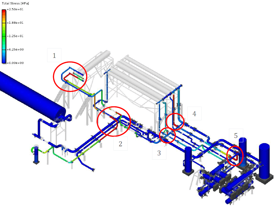
The most critical finding was the identification of several locations with potential for elevated cyclic stress amplitudes, especially near structural discontinuities and connection points:
- Downstream of air cooler E-1832 (outlet tee connection),
- At the valve connection between inlet and outlet lines for E-1832,
- PSV outlet line to vent connection,
- Elbow in the suction line to the second stage separator.
Peak cyclic stresses at these locations approached or exceeded the initial design guideline of 25 MPa amplitude. While these stress levels represent worst-case scenarios, the persistence of high stresses under frequency variation suggests a non-negligible risk of fatigue damage during prolonged operation.
Vibration and Shaking Forces
Although vibration levels at certain locations were sufficient to be visually observable, all predicted cyclic stresses for the analyzed operating modes remained within the 180 MPa (peak-to-peak) limit set by API 618, demonstrating compliance from an integrity perspective. The calculated shaking forces, particularly at the first and second compressor harmonics, were significant but did not lead to resonant excitation of the mechanical system due to adequate separation between acoustic and mechanical natural frequencies.
Mitigation and Design Recommendations
Multi-bore Restricting Orifices
It was recommended to replace the current single-bore orifice plates with multi-bore designs, particularly between the compressor and PSDs. Multi-bore orifices offer superior high-frequency damping, helping to control acoustic resonance modes that can otherwise amplify pulsations at the compressor flanges and valves, potentially shortening valve life and degrading compressor reliability. This mitigation addresses analysis limitations in BOSpulse, which may underestimate high-frequency resonance effects.
Structural Modifications
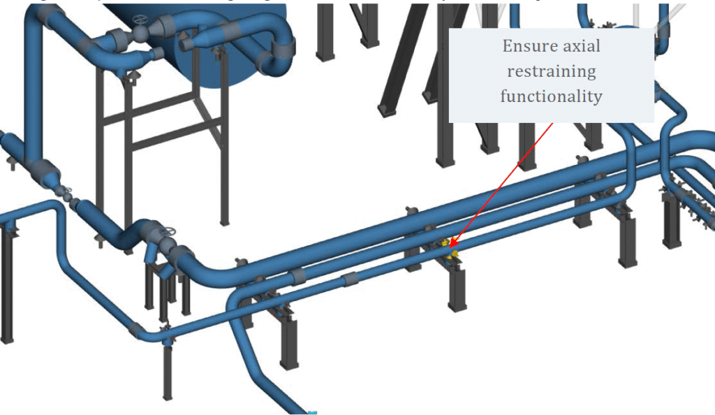
To further reduce cyclic stress amplitudes, targeted support and structural improvements were proposed:
- Increasing axial restraint and support stiffness downstream of air cooler E-1832,
- Implementing zero-clearance axial supports in the discharge line to the scrubber,
- Adding diagonal bracing in the third stage discharge line,
- Welding stiffener plates inside I-beam supports in the second stage suction line.
After implementing these mitigations, the maximum predicted cyclic stress amplitude was reduced to 20.3 MPa, restoring a robust margin against fatigue even under worst-case excitation scenarios.

Conclusions and Impact
The DA3 study confirmed that, with the recommended design enhancements, the Q8 Terminal compressor piping system complies with API 618 criteria for cyclic stress, pulsation, and vibration. The system’s safety and mechanical integrity are not compromised by the localized exceedances in pulsation amplitude and pressure drop, though these do highlight areas for efficiency improvement and risk reduction. The identification and mitigation of high cyclic stress locations underscore the importance of dynamic analysis and proactive design intervention in reciprocating compressor applications.
This case demonstrates the value of a comprehensive, simulation-driven approach to compressor station design, ensuring code compliance, operational reliability, and minimized risk of fatigue-related failure. The adoption of multi-bore orifices and targeted structural improvements will extend equipment life, reduce maintenance, and safeguard production continuity for the Q8 Terminal.