Phone: +31 (0)85 058 0046
E-mail: infoaanvraag@dynaflow.com
E-mail: infoaanvraag@dynaflow.com
ABOUT US
HEAD OFFICE
Laan van Oversteen 20
6th floor
2289 CX Rijswijk
The Netherlands
Vibrations are a common and potentially harmful problem in piping systems and process equipment. It is almost unavoidable that some level of vibration occurs in piping and equipment while in operation. Pressure pulsations are intrinsically present because compressors and pumps drive the flow. Small imperfections in equipment can introduce vibrations in the pipe and pipe fittings. Furthermore, valves always generate a certain level of flow disturbance, resulting in the presence of small pressure fluctuations. Small vibrations are often acceptable. Depending on the excitation mechanism and mechanical response of the system, however, fatigue failure may occur. For vibration-related failures, fatigue is the primary failure mechanism.
Vibrations can have many different sources. For vibration systems where the vibration source and mitigation measure are obvious, further analysis may not be required. In case of a more complex vibration problem, it is key to determine the source of the excitation. Typical sources include:
Proper mitigation, in the case of excessive vibrations, is important in the prevention of fatigue failures. DRG specializes in vibration-related issues while making use of the Energy Institute Guidelines. Dynaflow can perform vibration measurements, modal analysis, and a mechanical response analysis to determine the source of the vibration and the necessary mitigation measures.

The latest software and technical innovations like Vibassist’s Motion Amplification are used by Dynaflow to be able to perform the most accurate vibration analysis.

Dynaflow is very flexible and can quickly react and perform vibration measurements on-site.
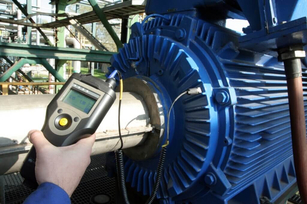
For the assessment of vibration problems in piping often vibration measurements are required. For the initial measurements, Dynaflow uses its vibration sensors to be able to inspect and efficiently capture important data quickly.
The dynamic analysis required for the assessment of piping vibrations is set up from a static piping model that is constructed with extra care for the correct stiffness and mass distribution.
The forced vibration is applied so that it corresponds to the vibration source of the actual model. The vibrations of the model are matched to the measurement results. From the replicated vibrations in the digital model, the dynamic stresses in the system are determined.
The vibration analysis can be performed using the time history profile of the vibration or, when the vibrations are more random, using a spectrum profile of the vibration. In this case, the time history profile from the measurements is converted into the frequency spectrum. The dynamic forcing amplitude is then scaled to match the maximum displacement of the displacement time history obtained from the measurements.
In case the time history profile can be used for the analysis directly, the mechanical response is fine-tuned and tuned to the measurement data.
Process equipment like pulsation dampeners or reactor vessels are often checked for vibrations in the design phase. In this case, the primary objective of the study is to make sure that the Eigenfrequencies in the shell of the vessel do not coincide with the loading frequencies related to the process properties.
An FEA (Finite Element Analysis) model of the vessel is developed. In the case where the assessment is performed for a vessel in operation, the wall thickness of the partly corroded shell needs to be used in the analysis for accurate results.
With a modal analysis, the Eigenfrequencies and Eigenmodes of the vessel are calculated. If the Eigenfrequency of the vessel matches the process-related loading frequency, the Eigenfrequency of the system is raised by e.g. adding stiffener rings to the vessel’s shell. This will move the Eigenfrequency of the vessel away from the loading frequency and subsequently limit the vibration amplitudes.
When there is enough clearance between the vessel’s Eigenfrequency and the loading frequency, a forced mechanical response analysis may be performed to verify that the vibrational stresses are within allowable limits and conform to the applicable design codes.
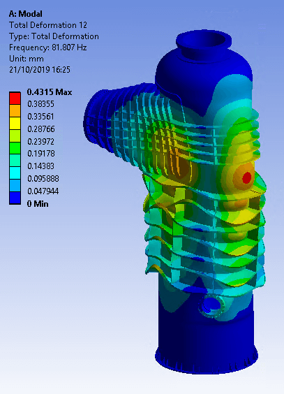
For a modal analysis, a digital representation of the physical (vibrating) system is developed using a FEM software package. In a modal analysis, the objective is to identify the natural vibration of the system. For accurate results, it is important to match the mass and stiffness distribution of the system. The output of the modal analysis is the Eigenfrequencies and Eigenmodes of the system that is being assessed.
The effectiveness of the excitation to cause vibrations, and the corresponding failure mechanism, is determined by the mechanical response of the system. In the case where the loading frequency matches the eigenfrequency of the system resonance may occur. Due to some level of damping that is always present in reality, this does not mean infinite excitation will occur. A match between the loading frequency and Eigenfrequency however is likely to amplify the oscillations of the system to levels where mechanical failure is to be expected.
The actual response of the system depends on the level of damping present in the system. Dynaflow can help determine the mechanical response of the system and whether mechanical problems are to be expected. The mechanical assessment is performed according to ASME VIII division 2 or EN13445 for equipment or ASME B31.3 or EN13480 for piping.
When mechanical failure is expected, Dynaflow can help reduce vibrations. By adjusting the weight distribution and stiffness of the system the Eigenfrequency can be moved away from the loading frequency to assure that resonance and the resulting large vibration amplitudes can be avoided. Re-designs are always proposed in close consultation with the client to make a design that is optimal from both a technical and a cost point-of-view.
Dynaflow can conduct vibration measurements and assessments. This is recommended for critical systems or for systems that are susceptible to vibrational issues and that have not been analyzed during the design phase of the system.
When the vibration source is known an equivalent model of the piping system or equipment is built and the calculated vibration is matched to the actual vibrations using a forced vibration applied according to the source of the vibration.
For a good match between the digital model and the physical system, vibration measurements may be required. The applied load amplitude is then fine-tuned to match the displacements in the model to the calculated displacements from the measurements of the actual system. In this case, the source of the vibrations must be known.
Advanced techniques like motion amplification of high-speed video data are used by Dynaflow to obtain an even better match between model and reality. While conventional vibration measurements give a lot of information about a specific location, motion amplification videos can help put this in a broader perspective.
Dynaflow specializes in vibration problems and can assist in quantifying the vibrations and determining the necessity and type of action to mitigate the vibration.
DRG conducts piping flexibility assessments using the software Caesar II from Hexagon. Caesar II is used for both static and dynamic piping analyses. We have a thorough understanding of the software and are also an official Caesar II training provider for Hexagon. Caesar II is considered the industry standard for pipe stress analysis.
Laan van Oversteen 20
6th floor
2289 CX Rijswijk
The Netherlands
© Dynaflow Research Group BV