Piping Vibration Analysis
Vibrations in piping systems result from interactions between the transported medium and the system’s mechanical properties, leading to energy loss, noise, and fatigue-related failures
Dynaflow Research Group addresses these issues through vibration measurements, modal analyses, and mechanical response studies, identifying root causes via structural and transient flow analyses. Flow variations in pumps, compressors, or process conditions can cause harmful pulsations and fatigue failures.
Effective system design is essential to prevent these problems, and Dynaflow’s expertise ensures reliable, efficient piping systems by mitigating vibration risks and enhancing overall performance.

CHALLENGES WE SOLVE
Resolving Complex Piping Vibration and Flow Challenges
- Pulsations from reciprocating or rotating compressors
- Flow-induced turbulence (FIT) or vibrations (FIV)
- Flow-induced pulsations
- Acoustic-induced vibration (AIV)
- Vortex shedding and vortex-induced vibrations
- Slug flow and multi-phase flows
- Machine vibrations
VIBRATION ANALYSIS PROCESS
Comprehensive Piping Vibration Analysis and Mitigation Solutions
Screening of the system during the design phase
All system lines are screened for FIV, AIV, and flow-induced pulsation risks using line sizes, geometry, and operating conditions. The study provides a Likelihood of Failure (LOF) value to assess the need for mitigation measures. The screening follows the Energy Institute Guideline methodology for accurate vibration prevention.
RE-DESIGN OF THE SYSTEM
Our team proposes re-designs to reduce the system’s Likelihood of Failure (LOF) to safe levels. These solutions target vibration sources or pipework responses and are developed collaboratively with clients to ensure technically effective and cost-efficient designs tailored to meet both performance and budgetary requirements.
Detailed analysis and mitigation of existing systems
When initial screening is too conservative or redesigns are impractical, Dynaflow conducts detailed analyses of specific concerns. This approach reduces conservatism from earlier analyses, potentially eliminating the need for system changes or enabling targeted, problem-specific redesigns for optimal solutions.
Piping vibrational assessment and mitigation
Dynaflow conducts vibration assessments for critical or vibration-prone systems not analyzed during design. Measurements align digital models with physical systems by fine-tuning load amplitudes. Advanced techniques, like motion amplification, enhance accuracy, requiring known vibration sources for effective analysis.
APPLICATIONS
Vibration Analysis Project Examples
For the assessment of vibration problems in piping often vibration measurements are required. For the initial measurements, Dynaflow uses its vibration sensors to be able to inspect and efficiently capture important data quickly.
The dynamic analysis required for the assessment of piping vibrations is set up from a static piping model that is constructed with extra care for the correct stiffness and mass distribution.
The forced vibration is applied so that it corresponds to the vibration source of the actual model. The vibrations of the model are matched to the measurement results. From the replicated vibrations in the digital model, the dynamic stresses in the system are determined.
The vibration analysis can be performed using the time history profile of the vibration or, when the vibrations are more random, using a spectrum profile of the vibration. In this case, the time history profile from the measurements is converted into the frequency spectrum. The dynamic forcing amplitude is then scaled to match the maximum displacement of the displacement time history obtained from the measurements.
In case the time history profile can be used for the analysis directly, the mechanical response is fine-tuned and tuned to the measurement data.

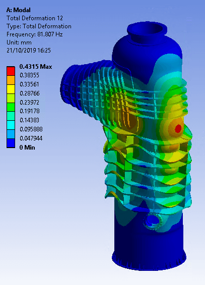
Process equipment like pulsation dampeners or reactor vessels are often checked for vibrations in the design phase. In this case, the primary objective of the study is to make sure that the Eigenfrequencies in the shell of the vessel do not coincide with the loading frequencies related to the process properties.
An FEA (Finite Element Analysis) model of the vessel is developed. In the case where the assessment is performed for a vessel in operation, the wall thickness of the partly corroded shell needs to be used in the analysis for accurate results.
With a modal analysis, the Eigenfrequencies and Eigenmodes of the vessel are calculated. If the Eigenfrequency of the vessel matches the process-related loading frequency, the Eigenfrequency of the system is raised by e.g. adding stiffener rings to the vessel’s shell. This will move the Eigenfrequency of the vessel away from the loading frequency and subsequently limit the vibration amplitudes.
When there is enough clearance between the vessel’s Eigenfrequency and the loading frequency, a forced mechanical response analysis may be performed to verify that the vibrational stresses are within allowable limits and conform to the applicable design codes.