Phone: +31 (0)85 058 0046
E-mail: infoaanvraag@dynaflow.com
E-mail: infoaanvraag@dynaflow.com
ABOUT US
HEAD OFFICE
Laan van Oversteen 20
6th floor
2289 CX Rijswijk
The Netherlands
When a standard design-by-rules approach outlined in pressure vessel codes is not sufficient to analyze the geometry of your equipment, finite element analysis (FEA) can provide a solution. With FEA it is possible to design your equipment against cyclic thermal loading or to design a nozzle with gussets that is right next to a discontinuity. The calculation can be performed for non-linear material properties or impulse loads in the order of microseconds.
An accurate 3D model of the relevant components is required for accurate results of the areas of interest. Especially when the temperature or stress gradient is high, a fine mesh is required. Whereas for uniform stress states or slow gradients, a less fine mesh is required. If there is enough distance between components, isolated models can be constructed to reduce complexity and calculation time.
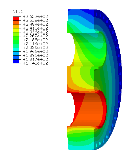
In the case of thermal loads, an accurate stress distribution throughout the component can be determined using FEA. A steady state temperature distribution can be determined or when thermal loads are varying because of cyclic conditions, the transient thermal distributions can be determined. In those cases, often multiple stress analyses are required because the most critical temperature distribution cannot always be identified beforehand.
The determination of (transient) thermal boundary conditions is a key part of any thermal FEA analysis. For thermal stress analysis usually brick-type FE models are used to capture (non-linear) thermal stress patterns induced by temperature gradients in the wall. Stress linearization is used to separate different stress categories and perform valid stress assessments. For the thermal distribution, we ensure a conservative but credible case, which is either based on HTRI results, analytical calculations, or detailed flow calculations using CFD.
At Dynaflow Research Group we are experienced with a wide range of finite element studies on a broad range of components. We regularly perform finite element analyses and assessments according to ASME VIII div. 2 part 5 or EN 13445-3 design codes.

Develop better products faster by reducing the number of physical prototypes while minimizing costs.

When complex geometries can no longer be analyzed with design by rules formulae, FEA will always provide an answer.

Dynaflow Research Group has over 35 years of experience with FEA and assessments according to the ASME VIII div. 2 part 5 or the EN 13445-3 design codes.
When equipment is subjected to cyclic loading due to alternating process conditions, vibrations, pulsations, or daily startup routines, it has to be tested against the required ASME or EN codes for (high-cycle) fatigue and ratcheting (also referred to as low-cycle fatigue). Typical equipment where potential fatigue-inducing stresses are present are heat exchangers, boilers, separators, air coolers, compressors, etc.
High-cycle fatigue can lead to the accumulation of microstrain, crack initiation, or crack growth. Fatigue cracks will increase in size after each cycle until they eventually cause failure. Low-cycle fatigue or ratcheting on the other hand usually occurs after a limited number of cycles, typically smaller than 7000. Failure is caused by the build-up of plastic strain after each cycle.
Using FEA methods, both low-cycle and high-cycle fatigue can be assessed. For low-cycle fatigue typically an elastic analysis is performed. It however is also possible to perform this type of analysis with a plastic material definition where the actual build-up of plastic strain can be captured.
In a high cycle fatigue analysis, the operating cases between which the component cycles are considered. The acceptability of the resulting stress histogram is tested to conform to the applicable S-N or fatigue curve. The output shows the acceptable number of stress cycles. In some cases, the cyclic loads occur at elevated temperatures in the creep regime. In these cases, the combined creep and fatigue damage is determined according to API 579.
A fatigue analysis will aid in designing equipment for a given operational life. This analysis can also be approached from the other way around, though. When the equipment is already in use but shows some signs of wear or corrosion, a fitness for service (FFS) check can be performed. This will tell how long the equipment can still be operational under the current conditions. This type of analysis considers the expected past and future number of cycles.
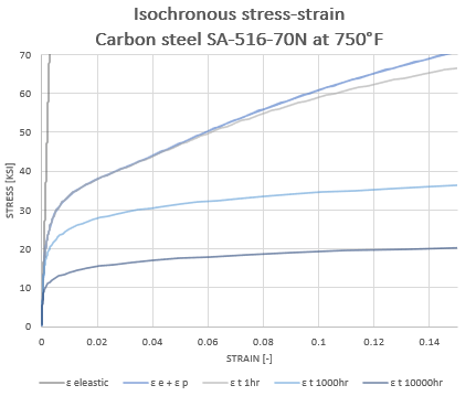
When components are operating under a high temperature or pressure, it is important to understand the effect of creep deformations. Creep is the tendency of a solid material to move slowly or deform permanently under the influence of stress well below the yield strength. It is a time-dependent deformation that does not occur suddenly under the application of stress. Rather, it is the accumulation of strain as a result of long-term stresses.
The ASME or EN allowable for secondary stresses is higher compared to primary stresses. With an elastic-plastic (non-linear) material model, stress categorization is not required. Stress redistribution is captured in the material model. Incorporating the non-linear material properties of the materials thus provides a more accurate assessment.
Hyperelastic materials like rubbers cannot be captured using a linear elastic analysis either. Although the deformation of these kinds of materials often stays within the elastic region, the stress-strain behavior is non-linear. With FEA this non-linear material behavior can be captured in detail. This increases the accuracy of the stress assessment
Usually, the results of a non-linear stress assessment are more optimistic because a more accurate material model is used. The safety factors to account for inaccuracies still apply, but are used to increase the applicable load, instead of reducing the allowable load.
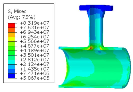
A piping system generally ensures that a fluid is transported from one place to another. On this journey, it is not uncommon that the piping system contains some tee junctions or nozzles. According to ASME B31.3, the flexibilities and Stress Intensification Factors (SIF) should be analytically determined according to ASME B31J, unless you have more applicable data. Although ASME B31J SIF and flexibility formulas are determined based on fatigue tests and FEA, the accuracy of a piping model can be improved using the FEA of the specific components in the system. With FEA the exact geometry can be taken into account to determine the flexibilities and SIFs, thereby enhancing the quality of the pipe stress model.
The calculated temperature distribution can be used as a boundary condition in the FEA model, together with the other loadings such as pressure and nozzle loads. With an elastic material model, the calculated stresses need to be categorized, it needs to be considered which load is primary (or weight driven) or secondary (displacement limited). It is important to consider which loads should be combined, for instance, what is the range for the startup/shutdown, or the operating cycle, or does the pressure load always act simultaneously with the thermal loading?
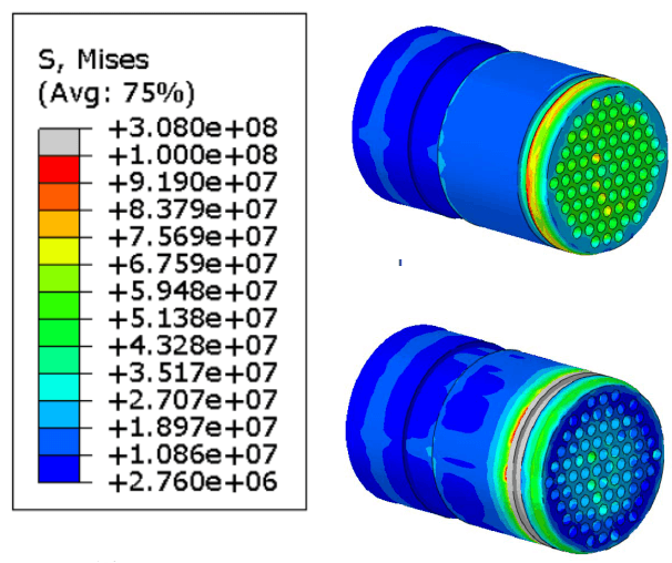
Thermal analyses of heat exchangers are concerned with the determination of the heat transfer rates and fluid outlet temperatures for a prescribed inlet temperature, heat transfer area, and flow passage dimensions. This way the effectiveness of the heat exchanger can be judged and large temperature gradients, which may cause structural failure, are detected. To do so, it is important to identify the contribution of all heat transfer mechanisms to the total transfer of thermal energy. Conduction, through the structure as well as through air, radiation, and convection are considered.
Another aspect to be considered when designing or verifying heat exchangers is the performance over some time. Due to corrosion or fouling (the accumulation of undesirable substances on the surface, e.g. due to oxidation), the surfaces tend to acquire additional heat transfer resistance that increases with time, hence reducing the efficiency of the system.
Conventional thermal analysis calculations (HTRI) are performed using classic formulae where the heat transfer coefficients are determined using experimental relations. This approach has proven to yield reliable results for standard equipment. However, for unconventional designs, the reliability of such methods decreases rapidly.
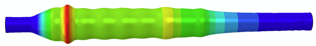
Explosion shock waves are assessed as impulse pressure waves with an almost instant pressure rise. This fast pressure rise causes the DLF of an equivalent static pressure to be smaller than 1. The value of this DLF and the behavior of components loaded by explosive pressures can be assessed using FEA.
The fact that an impulsive load has a DLF smaller than 1, causes thin-walled pipe to be able to accommodate internal explosions with pressures that would cause pipe rupture if applied statically.
The fast application of explosive pressures also causes dynamic behavior of the equipment. Although the application is not repetitive in the sense that it can cause resonance, it does cause rippling in thin-walled piping similar to a transverse wave that occurs when moving the end of a rope up and down. In thicker pipes, the resistance to this rippling is larger and is less likely to occur. In the analysis it will be visible as an oscillating stress field, that does not cause plastic deformation.
Although piping and equipment can most likely accommodate explosive pressure, it will likely deform plastically beyond the point where it can continue its operation.
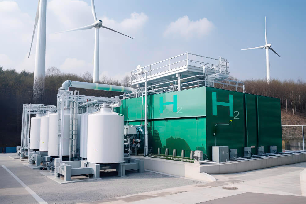
Hydrogen generation equipment has an inherent risk for internal explosions, posing an issue to safety. The hydrogen piping and equipment are required to withstand internal explosions by limiting the damage to deformation. Although this disqualifies the component for future use, safety is not compromised.
For this project, DRG was tasked with finding a correlation between the data obtained from the explosion tests and simulations performed by the client and static pressure values that help prove compliance through static pressure tests.
FEPipe is a template-based software solution specifically designed for use in the pressure vessel and piping (PVP) industry. Based on the chosen template, FEPipe performs detailed simulations using Finite Element Analysis (FEA) to comply with the ASME B&PV Section VIII Division 2. What separates FEPipe from general-purpose FEA software packages is its ability to rapidly construct PVP geometries and produce ASME code-compliant reports.
Abaqus is a robust general-purpose FEA software package. With Abaqus, it is possible to model and asses virtually any real-world problem for a wide range of industries. Abaqus has an extensive library with a wide range of element types and materials. It also allows the specification of custom materials. In addition to stress analysis, Abaqus can be used for convective and conductive heat transfer calculations, modal analyses, acoustics, and more.
Laan van Oversteen 20
6th floor
2289 CX Rijswijk
The Netherlands
© Dynaflow Research Group BV