
Table of Contents
Thorough steady-state, transient, 2D, And 3D Modeling Of Piping System
With BOSfluids, you have a solid platform to analyze a wide range of flow conditions in piping systems. Whether you are interested in steady state or transient flow conditions, gases or liquids, or very large or small piping systems, BOSfluids can handle all these cases efficiently and accurately.
The steady-state capabilities of BOSfluids enable you to accurately model pressure losses and flow rates in arbitrarily complex piping systems. When the system is filled with gas, you can make use of multiple equations of state to let BOSfluids determine the gas density throughout the system. The steady-state solver will automatically and recursively refine the piping model in areas where the pressure differences are relatively large. This ensures that BOSfluids yields accurate results irrespective of the way that the piping model has been set up.

The transient capabilities of BOSfluids enable you to assess a wide range of time-dependent flow conditions, including system startup and shutdown conditions, emergency conditions, and other changes in operating conditions. The transient solver applies state-of-the-art solution techniques to deliver accurate results quickly, enabling you to consider multiple scenarios in a short time frame. You do not need to be an expert in numerical simulations to obtain accurate results as the transient solver automatically tunes the relevant simulation parameters and checks for numerical errors by comparing the results obtained for different parameter values.
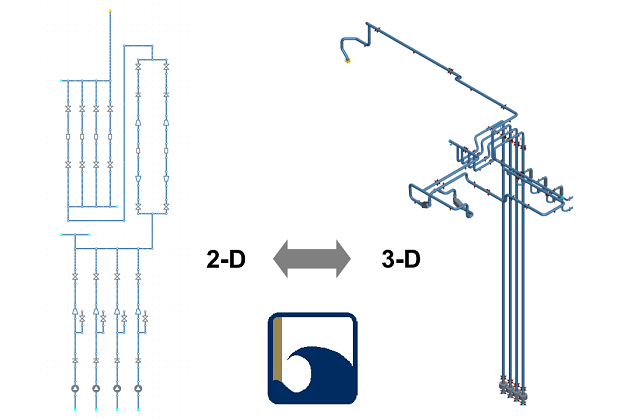
A unique feature of BOSfluids concerns support for modeling piping systems both as 2-D network models and as 3-D piping models. In the first case, you can concentrate on the topology and the main components of the system and ignore any details that are not relevant to the analyses to be performed. In the second case, you can correlate the piping model visually with the actual piping system and obtain detailed information about fluid-induced forces that are acting on the system. The support for 3-D piping models also aligns well with a trend involving the use of increasingly sophisticated CAD systems for designing and managing piping systems. In particular, BOSfluids is very good at importing CAD models through its Piping Component File interface.
Another unique and powerful feature offered by BOSfluids concerns support for the specification of model parameters as symbolic parameters instead of literal values. By varying the symbolic parameters in a parameter study, you can determine how the flow conditions are affected by those parameters and determine when the optimum conditions are obtained. You can also use this feature to create model templates that can be adjusted by simply assigning different values to the symbolic parameters.
Two-Phase Flood And Drain Model
The two-phase Flood & Drain model implemented by BOSfluids can be used to simulate the rapid filling of empty, or gas-filled, piping systems with a liquid. This makes BOSfluids a unique and effective tool for predicting the forces that are exerted by the liquid on the piping system. These forces can be significant, especially when the liquid hits a significant flow restriction or the end point of a pipeline section. Indeed, there have been multiple incidents involving firewater systems in which these forces caused significant damage to the piping system.
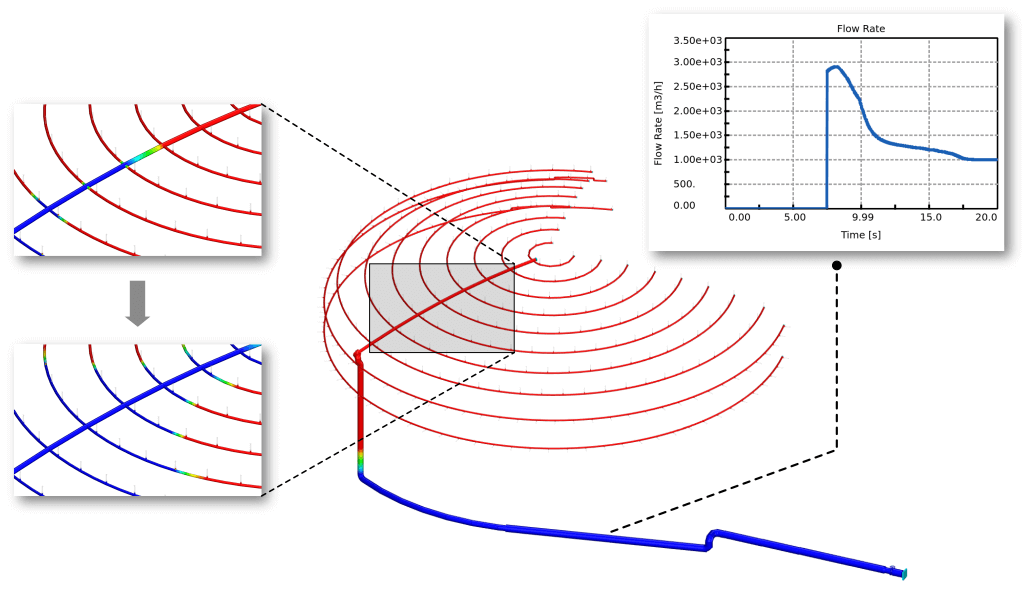
The Flood & Drain model can be used, among others, to simulate the flooding of dry firewater systems and the draining of fuel systems by flushing them with gas. The piping system may have an arbitrary complex topology as BOSfluids can handle the breaking up and merging of multiple gas volumes. The pressure within each gas volume is assumed to be equal throughout the entire volume but will change in time as the volume moves through the system and interacts with nozzles, sprinklres, check valves and air valves. When a gas volume passes through an inline restriction, such as a partly-closed valve, then it will be automatically broken into two so that significant pressure losses in the gas phase are accurately accounted for.
Because the model has been implemented in a flexible way, the flood and drain model can also be used to simulate other types of flow conditions involving a clear interface between the gas and liquid phase. For instance, you can use the model to simulate slug loads, vacuum waste water systems, and vessel blow-down scenarios.


The flood and drain model extends the scope of BOSfluids from simulating single-phase transient flow phenomena to a limited but important range of two-phase flow phenomena. It does that with the computational efficiency that you might expect from BOSfluids so that you can perform flood and drain analyses of complex and large piping systems in more or less the same time that a single-phase transient analysis would take.

Simulation Of Flow Equipment And Control
Flow conditions in piping systems, and especially transient conditions, are significantly affected by fittings, flow devices, equipment, and control systems. BOSfluids therefore comes with a large collection of flow element types that can simulate the pressure losses associated with these devices, as well as their static and dynamic behavior. Device-specific output data, reports, and graph types can provide you with a better understanding of their effect on the flow conditions.
Fittings
BOSfluids accurately accounts for the pressure losses associated with common fittings, including elbows, tee junctions, and reducers. In particular, BOSfluids automatically applies minor loss coefficients based on the fitting geometry and local flow conditions. Pressure loss coefficients associated with orifice plates, both single-hole and multi-hole plates, can be specified manually or can be calculated automatically using the ISO 5167 calculation method. BOSfluids also incorporates a model for simulating the discharge of gas or liquid through a deluge nozzle. This is typically used in conjunction with the two-phase flood & drain model.
Valves
Various element types can be used to model common valves and special-purpose valves, including check valves, air valves, and safety relief valves. When modeling a common valve, such as a globe valve or ball valve, you can select either a built-in pressure loss curve or specify one yourself. You can also specify an arbitrary opening curve that determines the valve opening as a function of time.
BOSfluids provides various options for modeling the dynamic behavior of check valves. The most straightforward, but not necessarily most accurate or conservative approach is to assume that a check valve closes instantaneously when reverse flow occurs. Alternatively, you can select detailed models of swing and axial (linear) check valves. These models simulate the dynamic motion of the closing mechanism and accurately account for the relative velocity of the closing mechanism with respect to the flow velocity. In the case that you have no detailed information about the closing mechanism, you can select a generic check valve model that is based on experimental check valve performance dynamic characteristics.


The air valve model in BOSfluids can simulate the intake of air when the pressure drops below the ambient pressure and the discharge of air when the pressure subsequently rises above the ambient pressure. The model supports the simulation of non-return air valves, triple function air valves and the specification of an initial air volume located at a valve. It can handle both normal and critical flow of air through the opening to the environment. Two models are available to determine the air flow rate as function of the pressure difference: a model based on the specification of nozzle diameters and discharge coefficients, and a model on a flow-pressure curve. The former also allows you to control the outlet nozzle opening as function of the air volume.
The safety relief valve model in BOSfluids is based on the methodology described by the API Recommended Practice 520. The model can handle single-phase liquids and gases, and liquids that undergo a phase transition due to flashing. The model accurately accounts for choking when the flow becomes critical.
Equipment
With BOSfluids, you can accurately model the flow of a fluid through axial (or centrifugal) and reciprocating pumps and compressors, generic equipment, and shell-and-tube heat exchangers. The axial pump model provides support for specifying a single pump curve or a complete pump map that can be described either in terms of pressure or in terms of head. If no information is available you can let BOSfluids generate a typical pump curve based on a collection of built-in pump curves. The pump model also supports the specification of a time-dependent running speed and the simulation of pump failure events. A dedicated pump plot can graphically show the operating point of a pump, both in steady-state and transient analyses.

The compressor model enables you to specify a compressor map in terms of the (absolute) pressure ratio and the flow rate at some standard conditions. If you specify a surge line or choke line, BOSfluids will calculate the amount of time spent in surge or choking conditions when performing a transient analysis. This can also be depicted graphically using a compressor plot.
The reciprocating pump and compressor models make it possible to accurately simulate the suction and discharge flow rates associated with one or more cylinders. Different options are available to specify the way in which the opening state of the suction and discharge valves are determined. An optional speed curve can be used to vary the running speed during a transient simulation.
A generic equipment element type enables you to model arbitrary relations between the flow rate through the equipment and the pressure drop over the equipment. You can also specify rated flow conditions and let BOSfluids determine the associated pressure loss coefficient. The latter will be applied automatically in transient analyses.
A heat exchanger element type can be used to simulate the flow through a tube-and-shell heat exchanger. This element type can be used to model both the flow through the shell and the flow through the tubes. The pressure drop over the heat exchanger can be calculated automatically through the tube of shell wall friction, but you can also specify a rated pressure drop at a rated flow rate.
Vessels
With BOSfluids, you can model gas-filled surge vessels and liquid-filled storage vessels (tanks). The surge vessel model simulates a polytropic process according to which the gas volume varies with the line pressure. A vessel can be closed or vented to the environment. In the latter case, air can be drawn into the vessel when its pressure drops below the ambient pressure. The initial gas conditions (pressure and volume) can be specified at steady state conditions or installation conditions.
The tank model enables you to specify a pressure boundary condition that depends on the height of the liquid in the tank. During a transient analysis, BOSfluids will adjust the level of the liquid in the tank according to the flow into or out of the tank. You can select a cylindrical shape or specify a custom profile that relates the cross-sectional area to the tank height. In this way, you can account for internal volumes that are to be excluded from the effective tank volume.

Control Systems
BOSfluids provides extensive support for simulating automatic control systems that adjust flow elements in response to changes in the flow conditions or to external events. This support comes in the form of a regulator valve element and a framework for implementing custom control systems. With the regulator valve element type, you can simulate a valve in which the opening is adjusted according to a set pressure or flow rate somewhere else in the piping system. You can use this element type both in steady-state and transient analyses.

The control system framework comprises sensors, transfer functions, and controllers that you can combine by writing arbitrary control rules in the form of user-defined subroutines. This provides you with an enormous amount of freedom to implement control systems that range from trivial switches to sophisticated PID controllers. In addition to that, BOSfluids will enable you to simulate control systems without having to perform a full flow analysis.
Tube Rupture Analysis
Tube rupture in a tube-and-shell heat exchanger can lead to overpressure situations in the shell or the tubes, especially if the high-pressure fluid is a gas or a liquid that undergoes a rapid phase transition due to flashing. The tube rupture model implemented by BOSfluids can be used to simulate the discharge of a high-pressure gas or liquid from one or more ruptured tubes into a low-pressure shell. The model supports phase transitions due to flashing, both at the fracture and within the tubes, and can handle both critical and sub-critical flow conditions. The model also accounts for pressure losses within the tubes and pressure changes due to temperature changes. When the tube-side fluid is a gas, then the Joule-Thomson effect is taken into account when determining the temperature and density of the discharged gas.
The tube rupture model can handle ruptures at the tube sheet or at an arbitrary point along the tubes. In the first case, the flow through one side of the rupture is viewed as flow through a nozzle, and the flow through the other side of the rupture is viewed as flow through an open-end pipe. In particular, the wall friction loss along the tube is accounted for. If the rupture is located somewhere along the tubes, then the flow through both sides of the rupture is viewed as flow through an open-end pipe.
The tube rupture model is complemented by models for safety devices such as relief valves and burst disks. Both models also support flashing and critical flow conditions. All these models make BOSfluids a versatile tool for the analysis of tube rupture scenarios.

Advanced Cavitation Modeling
The formation and collapse of vapor cavities is a common transient phenomenon that can have a significant effect on the evolution of the pressure in a piping system. BOSfluids therefore implements thorough support for cavitation modeling in the form of the Homogeneous Vapor Cavity Model (HVCM), the Discrete Vapor Cavity Model (DVCM) and the Discrete Gas Cavity Model (DGCM). The HVCM is relatively new and assumes that vapor cavities (bubbles) are dispersed homogeneously throughout the liquid, or collected in distinct, larger volumes, or combinations thereof. The DVCM and DGCM, on the other hand, assume that vapor or gas-filled cavities exist only at the flow grid points and that the cross-sectional area of a cavity equals the cross-sectional area of the pipe. Both the DVCM and DGCM have been described extensively in the literature.
If you intend to simulate the formation and collapse of vapor cavities, then the HVCM would be a good choice. This model, like the DVCM, does not require any additional input parameters and produces results that are in good agreement with experimental results. If there is reason to assume that the amount of entrained gas (air) is significant, then the DGCM would be the better choice.
All three cavitation models have been amended to handle cavities that span multiple grid cells. This unique feature makes it possible to accurately simulate the formation and collapse of large cavities in vertical piping sections, among others. All three models have also been modified so that they can be combined with the Flood & Drain model. The DVCM has been extended in such a way so that it can deal with slack-like flow conditions.

Support For Full Mechanical Response Analysis
Fast-changing flow conditions can lead to high and low pressures that can affect the integrity of the piping system. These conditions typically involve fast-changing and large pressure differences between opposite bends in the system. These, in turn, can result in significant forces acting on the piping system that can lead to mechanical failure.
BOSfluids can accurately predict the dynamic, fluid-induced forces acting on the piping system. Because BOSfluids works with 3-D piping models, it can predict the time-dependent magnitude, location and direction in which the forces act. Not only that, with BOSfluids you can perform a coupled fluid-structure analysis with a supported structural solver. This means that you can assess the effects of the fluid-induced forces on the piping system without leaving the BOSfluids interface.
Alternatively, you can export the forces in various formats, including those that can be im- ported by CAESAR II and Bentley AutoPIPE. All these features make BOSfluids a powerful and efficient tool for performing combined fluid-structure analyses involving piping systems.
A BOSfluids piping model is actually made up of a flow model and a structural model. The latter can not only comprise the usual pipe elements, but also different kinds of supports, structural steel elements, and tee junctions with associated geometry parameters, flexibility factors, stress intensification factors and sustained stress indices. This means that you can build one piping model in BOSfluids that can be used for both flow and structural analyses. This greatly reduces the need to build and maintain two different models in different software applications.


Exceptionally Fast And Accurate Solvers
With BOSfluids you have access to robust, efficient, and accurate flow solvers for both steady state and transient analyses. Both solvers can handle arbitrary complex and also very large piping models consisting of tens of thousands of pipe elements. The steady state solver implements an optimized non-linear solution procedure that can efficiently solve the non-linear flow equations. The use of advanced linear algebra techniques ensures that the solution process is executed in a small amount of time, even when dealing with large models. The transient solver is based on the widely-used method of characteristics to solve the time-dependent momentum and mass conservation equations.
Transient flow analyses involving large or detailed piping models traditionally take a substantial amount of time. BOSfluids therefore provides a very efficient transient solver that applies a novel grid coarsening method to reduce the analysis time dramatically without reducing the accuracy of the results. This method involves the use of a model optimizer that automatically aggregates adjacent pipe sections with identical properties. After that it generates a coarse computation flow grid where possible, and a fine grid where necessary. The result is a reduction in analysis time of up to two orders of magnitude for models involving both detailed parts and long pipeline sections.
To ensure that the computed results are accurate, the transient solver performs an automatic convergence check. This involves running two transient analyses with different flow grid resolutions, after which the solver will check whether the computed results are similar enough. If not, you will be notified so that you can adjust the default transient solution parameters to increase the accuracy of the results. The convergence check is an effective safety measure that prevents you from drawing the wrong conclusions based on inaccurate results and on models that are very sensitive to changes in model parameters.
BOSfluids can take advantage of multiple processor cores on different levels. On a high level, it will run the user interface on a different core than the flow solver so that you can view the results for one scenario while another is still being processed. On an intermediate level BOS- fluids will schedule different scenarios on different processor cores. On a low level, it will use multiple processor cores to reduce the time to run a single transient flow simulation. This all means that you have to spend less time waiting for results and that you can spend more time solving your flow problems.

Outstanding Support For Importing Piping Component Files And Other File Formats
While you can perfectly build complex piping models in BOSfluids, you can also import piping models from different file formats, including Piping Component Files, CAESAR II neutral files, EPANET and PIPENET model files, and spreadsheets defining pipe profiles. When you import a model, you can replace the current model, extend the current model, or update the current model by using the geometry defined by the imported model. The latter option is useful if you need to work with BOSfluids and another piping analysis tool on the same piping system.
Because BOSfluids fully supports working with 3-D piping models, it has exceptionally good support for importing Piping Component Files. When doing so, BOSfluids will apply various, automatic algorithms to correct common problems such as overlapping elements and disjoint elements. Various parameters are available to tweak the import algorithms so that you can end up with a correct and consistent piping model. Before importing a set of PCFs, you can specify the relevant geometry parameters for the piping specifications referred to in those PCFs. BOSfluids simplifies this process by automatically extracting a list of the piping specifications after you have selected the PCFs to be imported. This generally happens without any noticeable delay because efficiency has been an important requirement for the PCF interface in BOSfluids. It can easily handle hundreds and even thousands of PCFs that define a single piping model.
By using the element table editor you can export the parameters associated with a selection of elements to a spreadsheet. This editor also supports importing element parameters from a spreadsheet.


Effortless Modeling Of Operating Scenarios
BOSfluids enables you to define multiple scenarios in a single piping model. A scenario can be viewed as a context or scope in which the model parameters are defined. Multiple scenarios can be defined to study different variations of the piping model. For instance, if you are interested in the effects of a valve closure profile on the flow and pressure distribution you could define multiple scenarios that specify different closure profiles for that valve. In fact, you can change any model parameter, except the pipe geometry, in a scenario.
By default, a piping model comprises only one scenario, called the main scenario, that defines the primary model parameters and the piping geometry. Any other scenario is implicitly derived from the main scenario. That is, any change to the main scenario, such as a change in pipe diameter, is propagated to all other scenarios. On the other hand, a change to any scenario other than the main scenario only affects that particular scenario.
A BOSfluids model may comprise an unlimited number of scenarios. The user interface provides various tools for managing, editing and comparing the scenarios. In particular, you can make arbitrary scenario selections and edit them all simultaneously. Because BOSfluids only stores the differences between a scenario and the main scenario, adding a new scenario requires no additional storage or processing time.
You can perform analyses for multiple scenarios in parallel (if multiple processor cores are available) and compare the results from multiple scenarios in different ways. This can help you understand how important model parameters affect the flow conditions so that you can make informed decisions on system modifications and system design.


Integration With Key Pipe Stress And Mechanical Packages
The design or analysis of a piping system generally involves multiple software tools that focus on the flow conditions within the system and the structural behavior of the system. With BOSfluids you will have a tool that not only covers the first aspect but also plays well with pipe stress and mechanical software tools. In particular, the support for working with 3-D piping models means that the model in BOSfluids will be very similar to the model in pipe stress analysis software. This makes it much easier to exchange information, including fluid-induced forces, between BOSfluids and pipe stress software. It also greatly reduces the scope for modeling errors that can be introduced when exchanging data between software.
BOSfluids provides a thorough file interface for reading and writing CAESAR II neutral files, a file format that is supported by key pipe stress software packages, including CAESAR II, Bentley AutoPIPE, and CSiPlant. Using this file interface you can not only import and export the piping components but also supports and structural steel elements. This means that you can minimize the loss of information when going between BOSfluids and pipe stress software.
When you have made changes to a piping model in external software, you can import those changes into BOSfluids with the update geometry function. This function will update the geometry of the BOSfluids model while preserving all fluid-related parameters that are likely not to be available in the external model. This is another way in which BOSfluids can make you more productive when switching between software tools.

Extensive Reporting And Open-Standards Access To Analysis Results
The BOSfluids user interface provides a wide range of possibilities to view the results of one or multiple analyses. The results can be shown in different ways in the piping model itself. They can also be displayed in various types of plots, including min-max plots, profile plots, parameter variation plots, time history plots, frequency plots, and pump plots. The results are also available in textual form by means of a collection of standard reports and the possibility to generate custom reports containing the data of most interest.
With BOSfluids, you can share models and selected results with your clients while maintaining control over which data are made available. This involves exporting the model and results to the companion application BOSview which can be downloaded and used for free. BOSview is not only capable of displaying BOSfluids models and results but can also display piping models that are stored in different file formats, including Piping Component Files.
We strongly believe that the piping models you create should not be locked away in some propriety and inaccessible format. BOSfluids models and results are therefore stored in human- readable text files and HDF5 database files that can be accessed with free and open source tools. You can even access and modify these files from Python and Matlab scripts so that you can use BOSfluids as a building block in your own, custom solution procedures.
If your BOSfluids license has expired, you can still use BOSfluids to view your models and results. You can no longer, however, save any changes to your models or perform new flow analyses.


Resources Available

Training Courses
Learn all about the effects of pressure surges on piping systems and how to perform a surge analysis using BOSfluids.

Webinars
See BOSfluids in action in one of our webinars where we explore the latest uses cases and applications.

Knowledge Base
Check out the latest product releases and articles that answer your technical questions.