API 674 Analysis For Reciprocating Pumps
Pulsation analysis for reciprocating pumps (according to API 674) and centrifugal pumps
Reciprocating and centrifugal pumps are used to raise the pressure of a liquid medium. As with compressors, the oscillations from a reciprocating pump or the blade passing of a centrifugal pump will lead to pulsations in the flow upstream and downstream of the flow. The vibrations and dynamic loading due to these pulsations can lead to excessive loading and fatigue issues in the piping.
Dynaflow Research Group (DRG) can offer a complete range of solutions to assess how critical a pump is for the operation of your system. Our assessments can be used to assess a concept at the design stage or to solve a pulsation issue observed during operation.
The API 674 Design Code for Reciprocating Pumps
Typically reciprocating pumps will lead to significantly larger amplitude pressure pulsations than centrifugal pumps. Within the industry-standard API 674 design code, it is stated that the piping around a reciprocating pump should be analyzed to ensure that the piping is capable of withstanding the pulsations. For bespoke systems, where an identical version is not already in operation, this assessment should take the form of a calculation.
The API 674 design code provides guidelines for acceptable pulsation levels in the piping connected to a reciprocating pump.
If the pulsation amplitude remains within these levels, then experience has shown that the dynamic stress levels within the piping will not lead to fatigue issues.
The allowable pulsation amplitude according to the API 674 is dependent on the frequency. Thus, to determine the suitability of a system, it is necessary to assess all of the pump harmonics individually using a discrete Fourier analysis.


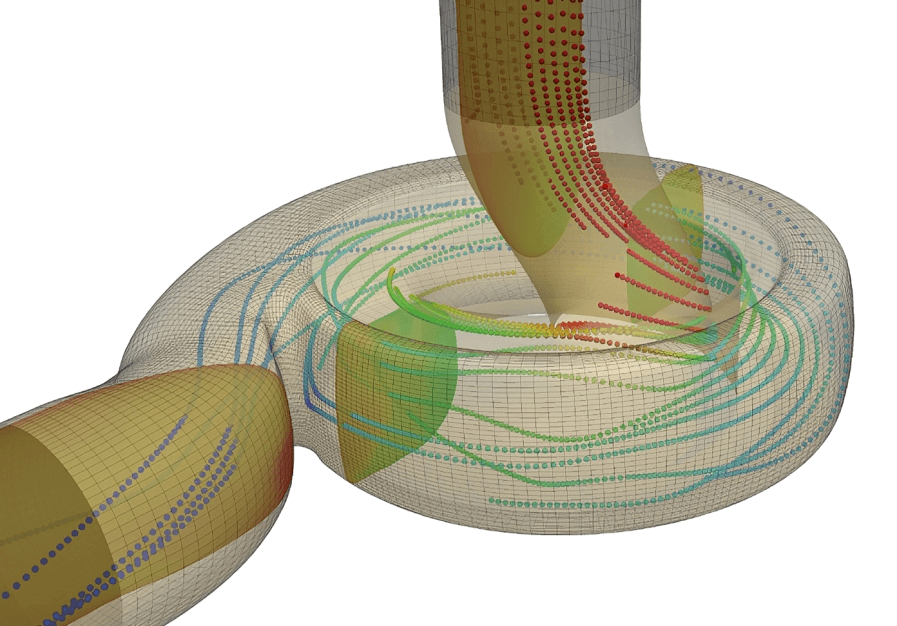
Computational Fluid Dynamics
Discover how we can support your Pulsation Analysis related projects
Case Study: Removing Vibrations in a Flow Station
Dynaflow Research Group (DRG) was asked by one of our clients to reduce the excessive, potentially fatigue-inducing, vibrations they were observing at one of their oil flow stations. These were seen in the suction and discharge headers for the reciprocating pumps, and the pump recirculation line.
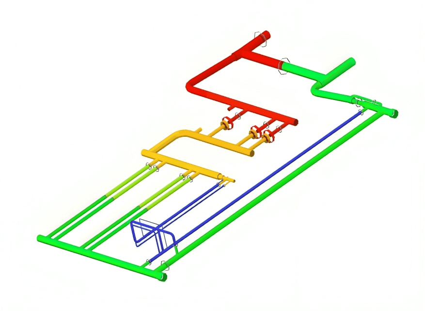
To find the cause of the observed vibrations and to determine what measures were required to rectify the problem, DRG performed a pulsation analysis combined with a mechanical response analysis. DRG worked with the client to obtain the information necessary to build a model of the system piping using the CAESAR II piping stress software. This model was used first to perform a scoping static stress assessment to verify if the existing pipe-supporting design was adequate.
To perform the pulsation analysis, a model of the fluid path within the flow station was then generated in BOSpulse. Here pulsations, according to the maximum amplitudes given in the API 674 design code, were applied at the location of the pumps. Using BOSpulse it was possible to calculate the pressure amplitudes within the downstream piping and determine if any acoustic resonance modes were being excited.
The pulsations due to the reciprocating pumps led to unbalanced forces within the piping system. These forces were used as an input for the mechanical response study. As a result of the analysis, it was found that the observed vibrations were likely to cause a fatigue problem. Consequently, DRG developed a revised supporting layout to ensure that all the piping could withstand the pulsation levels conforming to the API 674 design code
