Fiberglass Engineering
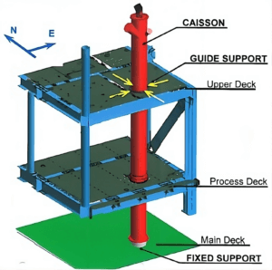
GRE Seawater Dump Cassion
Introduction In this case study, a finite element stress analysis was conducted on a seawater dump caisson installed on the deck of a floating offshore

Introduction In this case study, a finite element stress analysis was conducted on a seawater dump caisson installed on the deck of a floating offshore
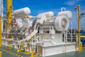
Introduction A plant in Asia requested a simulation study to be performed, both fluid mechanical (acoustical) and mechanical, of the compressor piping between the first

Introduction A serious crack next to a weld in the circulating water flow system was found but it was unclear what had caused this crack.

Dynaflow Research Group is pleased to announce the new major releases of all of the DRG software products, including BOSfluids, BOSpulse, ISOtracer, and BOSview. Version 7.1.

Dynaflow Research Group will be one of the exhibitors at TPS Turbomachinery & Pump Symposia (TPS) in Houston, Texas. TPS is a vital industry event,

On July 5th Dynaflow will organize a Software User Day. During this event participants will learn about new and upcoming features, discuss existing features and meet other

Recently Dynaflow Research Group together with online training platform EngineeringTrainer.com released “How to Review a Pulsation Study” training course. The course objective is to explain

In April of this year Dynaflow Research Group will present two papers at the International Conference on Pressure Surges.

Dynaflow Research Group will give a technical presentation during the SPE Symposium: Non-Metallics in Abu Dhabi February 2023.

We are pleased to announce that Frank Bos has been elected partner at Dynaflow Research Group.

From March 20th until March 24th, Dynaflow Research Group will collaborate with the Numerical Analysis group of the Department of Applied Mathematics at Delft University

We are glad to announce that the BOSfluids course has been updated. The course has been restructured and expanded to provide insights on the latest version of the BOSfluids program.
The basis for reliable fiberglass piping systems are the specifications that lay out the requirements to the system regarding material quality, engineering, installation and inspection and test plans.

Cooling water installations are designed to cool an installation in the event of a nearby fire. This can be necessary if the contents of a tank or pressure vessel are likely to expand with heat. We can use BOSfluids to perform hydraulic calculations of steady state flows in a cooling water system that includes many deluge nozzles (sprinklers).

The latest BOSfluids release brings a new, low-cost license option that is aimed at users who are primarily interested in performing steady state analyses.

Dynaflow Research Group has recently performed several level 1 and 3 assessments resulting in either extended service lifetimes or recommendation of component replacement.

The new BOSfluids release brings many small and large improvements to its user interface that make it even more efficient and versatile.
Dynaflow proudly presents a new online training course: “Pipe Stress Analysis”.
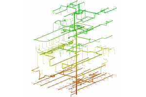
Dynaflow Research Group has performed the design and analysis for the firewater deluge layout of two large production modules of a floating production storage and
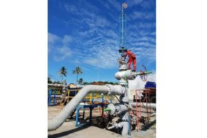
Two of the key challenges currently encountered in operating geothermal wells using conventional steel casings are corrosion and scaling. These problems significantly reduce the lifespan

Today Dynaflow Research Group will join the TU Delft Institute for Computational Science and Engineering (DCSE) in hosting an introductory course in the use of

Table of Contents A Good GRP Code Covers a Large Variety of Products and Loading Conditions A robust Glass Reinforced Plastic (GRP) piping code must
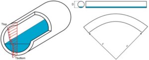
Thermal bowing is a structural phenomenon that arises when a temperature gradient exists across the cross-section of a pipe or vessel. In typical pipe design,

Table of Contents As the demand for flexible, energy-efficient, and reliable compressor operation grows—particularly in hydrogen and process gas applications—our clients increasingly turn to stepless

Table of Contents Multiphase flow is a recurring challenge in process engineering, where multiple fluid phases—such as gases, liquids, or solids—interact within a single flow

In the chemical and energy industries, liquid products such as LNG, ammonia, or naphtha are commonly transferred between ships and onshore storage tanks. These transfers
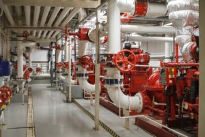
In the engineering domain, accurately simulating transient events in pipeline systems is critical, particularly for essential safety mechanisms such as firewater systems. These systems, typically

Introduction Pressure vessels are critical components in a wide range of industries, including power generation, petrochemical processing, and industrial manufacturing. These vessels are designed to
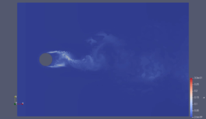
When Theodor von Kármán first discovered vortex shedding in 1911, he likely had no idea how pivotal his work would become for modern engineering, particularly
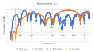
In a previous article, we introduced the risks and design considerations of repurposing an existing natural gas compressor system for hydrogen. That discussion focused on

ON-DEMAND 🕖 50 MIN 🌏︎ ENGLISH Acoustically Induced Fatigue in Gas Filled Piping Systems Using BOSfluids Remco Boere Senior Software Engineer Get instant access

ON-DEMAND 🕖 60 MIN 🌏︎ ENGLISH Simulation Strategies and Practical Application for Vapour Cavity Formation Dr. Ir. Erik Jan Lingen Software Director Get
ON-DEMAND 🕖 60 MIN 🌏︎ ENGLISH Fundamentals, Failure Mechanisms, and Engineering Consequences of Vapor Cavity Formation Dr. Ir. Erik Jan Lingen Software Director

ON-DEMAND 🕖 45 MIN 🌏︎ ENGLISH Bridging the Gap: From NFPA 15 Steady-State Design to Transient Surge Analysis in Tank Terminals Uri Peker

ON-DEMAND 🕖 45 MIN 🌏︎ ENGLISH Support Stiffness Effects on Mechanical Natural Frequencies in Reciprocating Compressor Piping Systems Thijs Krijger Project Engineer Get

ON-DEMAND 🕖 60 MIN 🌏︎ ENGLISH Beyond hydraulics: a practical guide to fire water analyses with BOSfluids Dr. Ir. Erik Jan Lingen Software
AIV Fundamentals At what pipe diameter and wall thickness should one be concerned about AIV? What is the relevant D/T ratio? This depends on the
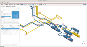
ON-DEMAND 🕖 3 SESSIONS x 45 MIN 🌏︎ ENGLISH Complete Pulsation Analysis Using BOSpulse Tim Gebraad Software Lead Engineer Marienne Faro Software Sales Engineer

ON-DEMAND 🕖 60 MIN 🌏︎ ENGLISH Getting the Timing Right: Why Time Step Size Is Critical In Surge Analysis Dr. Ir. Erik Jan
ON-DEMAND 🕖 30 MIN 🌏︎ ENGLISH Protecting Tank Terminal Assets Through Surge and FFS Analyses Thijs Krijger Project Engineer Katrine van Overhagen Engineer

ON-DEMAND 🕖 60 MIN 🌏︎ ENGLISH Choosing the right GRE piping standard: a comparison of ISO 14692 and ASME NM.2 Edwin Schimmel Project Engineer

ON-DEMAND 🕖 50 MIN 🌏︎ ENGLISH How Stepless Capacity Control Shapes Flow and Pulsations Thijs Krijger Project Engineer Get instant access Free. Recording

ON-DEMAND 🕖 60 MIN 🌏︎ ENGLISH Water Hammer Analysis & Mitigation in Pipeline Systems with BOSfluids Dr. Ir. Erik Jan Lingen Software Director

ON-DEMAND 🕖 60 MIN 🌏︎ ENGLISH Water Hammer Analysis & Mitigation in Pipeline Systems with BOSfluids Dr. Ir. Erik Jan Lingen Software Director

ON-DEMAND 🕖 35 MIN 🌏︎ ENGLISH Understanding, Modelling, and Managing Thermal Bowing using CAESAR II David Tickner Senior Engineer Get instant access Free.
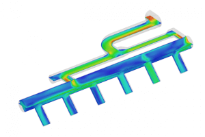
What are the key challenges in applying CFD to simulate and optimize multiphase processes in complex industrial systems? The main challenge here is the ability

Do CAESAR II formulas for thermal bowing and output results match with FEA? Short Answer: There can be significant differences between the results of CAESAR II and FEA.Explanation:The
ON-DEMAND 🕖 35 MIN 🌏︎ ENGLISH Using CFD for optimizing multiphase process engineering Bart van der Zalm Senior Engineer Get instant access Free.

DRG CONFERENCE – 35TH ANNIVERSARY 🌏︎ ENGLISH Innovations that Change the Engineering Industry Get instant access Free. Recording + slide deck available Event Description

ON-DEMAND 🕖 35 MIN 🌏︎ ENGLISH Fatigue Assessment According to ASME B&PV VIII Div.2 Lukas Bajarunas Senior Software Engineer Get instant access Free
ON-DEMAND 🕖 45 MIN 🌏︎ ENGLISH Fiberglass Piping Stress Envelope According to ISO 14692 using CAESAR II Edwin Schimmel Project Engineer Get instant
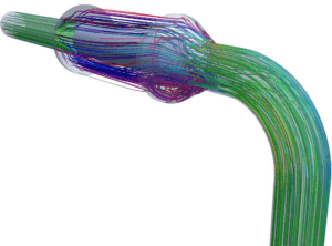
A Commissioning Failure That Sent Debris Downstream During commissioning of a natural gas compressor station, pieces of fibreglass fabric, mineral wool and steel wire were found throughout the downstream system. A small amount of mineral wool was also found in the surge valve. Inspection showed that the mineral wool found
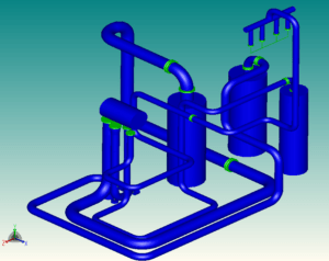
Compressor Piping Under Combined Marine and Process Loading The compressor module was located roughly halfway along the hull. Its connected piping had to accommodate thermal and pressure loads, wind loads, accelerations from wave-driven barge rocking and relative displacements from hull deformation. These loads could produce pipe deflection and bending and
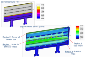
Cyclic Thermal Duty in a Gas Treatment Air Cooler An air-cooled heat exchanger for a gas treatment plant is subjected to a varying inlet temperature. In the analysed winter case, which has the largest temperature variation, the fluid cycles between 7.5°C and 288°C during each 100-minute cycle. The first part
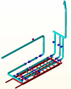
Consolidating Gas Flow onto a Single Metered Line A platform gas metering station has three parallel metering lines, two active and one spare. The modification replaces the orifice-type flow meter in the most eastern line with an ultrasonic (US) flow meter and directs the complete gas flow through that line.
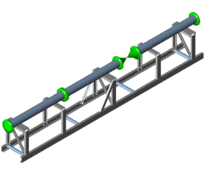
Nitrogen Skid Stress Verification Requirement A manufacturer produces a nitrogen metering skid for a project. As a result of a client performance requirement, the existing design had to be verified by stress analysis. The skid is a straight pipe configuration with valves and flow meters, supported approximately 1000 mm above
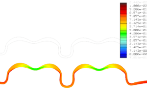
An axisymmetric finite element analysis checked the flued flange expansion joint of a fixed-fixed tubesheet reboiler for low cycle fatigue, high cycle fatigue and primary stress to ASME Section VIII Division 2, at mean (26 mm) and minimum (22 mm) wall thickness. The largest low cycle fatigue stress range was
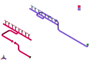
The station model of the Winksele Compressor Station, to be built in Belgium, was divided into two models with some mutual overlap, a compressor model and a filter model, each covered by a separate stress report. A third report covers the gas air coolers as model C, an add-on to
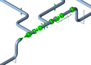
An additional separator was installed in Phase 2 of a cluster project and was to be connected to the existing lines through a modified above-ground (A/G) manifold. The manifold also connects to an existing buried (underground, or U/G) line. The analysis applied pressures of 100 / 225 Barg and temperature
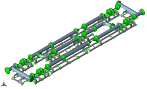
A combined CAESAR II model of a gas metering skid and its structural steel frames was assessed against ASME B31.3 (2006). The piping stresses were below the allowables, the steel stresses were within the allowable limits for the sustained and expansion load cases, and several bolt shear loads exceeded the
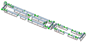
Multi-Mode Metering Skid with Undefined Connecting Piping The unit assessed was a 24-inch, 300# ethane metering skid. Gas can be routed through a normal operating line (line 1), a testing and maintenance line (line 2), two flow control lines (lines 3 and 4) and a bypass. No more than one
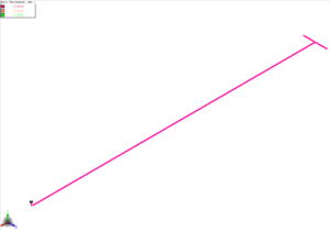
CAESAR II stress analysis of 13 critical sections of a buried GRP fire water system, to ISO 14692, expected no problems for the underground piping under pressure and temperature loads. High stresses occurred in vertical above-ground GRP pipes where the pipe is vertically restrained; in section D, guide and rest
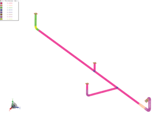
Seventeen underground GRE firewater subsystems at a degassing station were analysed in CAESAR II for three load cases, hydrotest, operational and sustained, to ISO 14692. It may be concluded that, upon implementation of the recommendations, the static pipe stresses are acceptable and the flange loads are moderate. Underground GRE Firewater
Thirteen buried GRE firewater subsystems were modelled in CAESAR II and assessed to ISO 14692 for hydrotest, operating and sustained load cases. On implementation of the recommendations, static pipe stresses are acceptable and flange loads are moderate. The buried glass-reinforced epoxy (GRE) piping in the firewater system upgrade at a
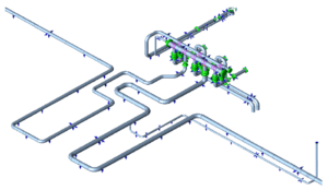
The main firewater line for a new oil terminal jetty is made from glass reinforced epoxy (GRE) pipe. It starts at the onshore transition between underground and above-ground pipe, where it connects to steel lines, and follows a jetty about 1.5 km long. A firefighting platform about one third of
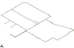
Static stress analysis of two buried GRE firewater subsystems in CAESAR II covered three load cases with a design pressure of 13.4 barg and a maximum design temperature of 40 °C. The stress analysis report, a preliminary issue, records wall thickness increases and polystyrene on five isometrics and concludes that,
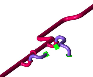
Nine underground GRE firewater systems, 77 stressed isometrics in total, were analysed in CAESAR II against the ISO 14692 allowable stress envelopes, with soil-pipe interaction modelled to the American Lifelines Alliance (2001) soil model. Modifications included a support bracing, polystyrene foam, NBR gasket stiffness limits and additional laminate for a
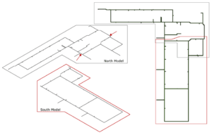
A CAESAR II static stress analysis of a buried GRE firewater network against ISO 14692 found 18 bends and 10 tees overstressed in the original design. In the modified models, all stress points are within the ISO 14692 envelopes for the sustained, operational and hydro load cases, provided the system
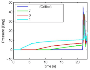
An underground storage station was being expanded with an additional compressor and a third injection well cluster, and the existing firewater package was being extended as part of the project. Two jockey pumps pressurise the system. When a blowout alarm is raised, the deluge valves open and the main firewater
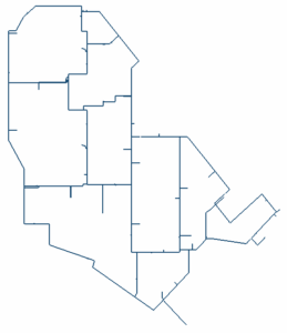
A buried GRE fire water ring was assessed in CAESAR II against the ISO 14692 allowable stress envelope. Static stresses stayed within the envelope for all load cases after additional lamination at nine bends, and the settlement analysis set a 4 MPa axial margin on the operational or occasional envelope.
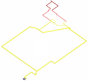
A new unit was added to an existing gas complex, and the firewater ring main was extended to serve it. Three sets of four 3-inch hydrant valves were modelled, twelve hydrants in total. Each hydrant is required to produce a minimum of 1452 l/min at 7.0 barg, and the hydrant
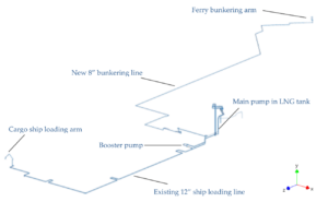
Extending an LNG terminal with a new cryogenic bunkering line At an LNG storage and loading terminal, a new line was constructed to supply liquefied natural gas directly to ferries. This 8-inch bunkering line branches from an existing 12-inch line that is used to load LNG into cargo ships. A

DYNAFLOW RESEARCH GROUP (“DRG”) Enters into Reseller Agreement with Quality Professional Software (“QPS”) RIJSWIJK, The Netherlands – January 24, 2024 (Dynaflow Research Group BV) –

Dynaflow Research Group and Seawind Ocean Technology announce collaboration focusing on technical readiness of floating offshore wind applications in the Mediterranean Sea. This landmark partnership