
Fluid Flow
Heat Exchangers in Concentrating Solar Power
DRG performs structural assessments on Heat Exchangers for Concentrating Solar Power plants The US Office of Energy Efficiency & Renewable Energy proclaimed 2014 ‘The year

DRG performs structural assessments on Heat Exchangers for Concentrating Solar Power plants The US Office of Energy Efficiency & Renewable Energy proclaimed 2014 ‘The year

Flow Assurance training course offers a valuable opportunity to learn from and seek advice from one of the foremost experts in Oil and Gas Flow

Presentations by keynote speaker Prof. Dr. ir. Ruud Henkes (Shell / TU Delft) and Dr. Andrew Jackson (Engys UK) The abstracts for the presentations by

Title: Vacuumatics: 3D Formwork Systems By Franciscus Antonius Augustinus Huijben One of the most important architectural trends of the last two decades is commonly referred

Titel: Computational Modelling of Particle Packing in Concrete By Huan He Physical particle packing is becoming a hot topic in concrete technology as more and

Titel: Porosity of Concrete – Morphological Study of Model Concrete By Jing Hu Porosity of Concrete has developed a comprehensive methodological framework for characterizing geometrical

Titel: Mesostructure of concrete Stereological analysis and some mechanical implications By Jianjun Zheng On the mesoscale, concrete can be considered as a composite material consisting

Table of Contents A Good GRP Code Covers a Large Variety of Products and Loading Conditions A robust Glass Reinforced Plastic (GRP) piping code must
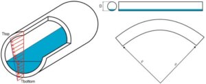
Thermal bowing is a structural phenomenon that arises when a temperature gradient exists across the cross-section of a pipe or vessel. In typical pipe design,

Table of Contents As the demand for flexible, energy-efficient, and reliable compressor operation grows—particularly in hydrogen and process gas applications—our clients increasingly turn to stepless

Table of Contents Multiphase flow is a recurring challenge in process engineering, where multiple fluid phases—such as gases, liquids, or solids—interact within a single flow

In the chemical and energy industries, liquid products such as LNG, ammonia, or naphtha are commonly transferred between ships and onshore storage tanks. These transfers
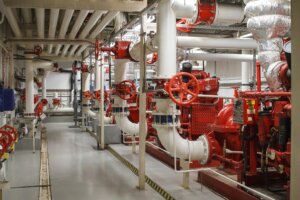
In the engineering domain, accurately simulating transient events in pipeline systems is critical, particularly for essential safety mechanisms such as firewater systems. These systems, typically

Introduction Pressure vessels are critical components in a wide range of industries, including power generation, petrochemical processing, and industrial manufacturing. These vessels are designed to
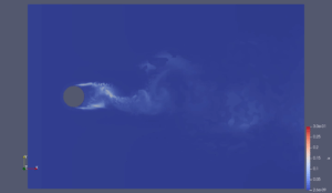
When Theodor von Kármán first discovered vortex shedding in 1911, he likely had no idea how pivotal his work would become for modern engineering, particularly
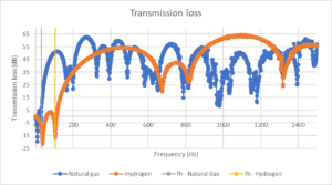
In a previous article, we introduced the risks and design considerations of repurposing an existing natural gas compressor system for hydrogen. That discussion focused on

ON-DEMAND 🕖 50 MIN 🌏︎ ENGLISH Acoustically Induced Fatigue in Gas Filled Piping Systems Using BOSfluids Remco Boere Senior Software Engineer Get instant access

ON-DEMAND 🕖 60 MIN 🌏︎ ENGLISH Simulation Strategies and Practical Application for Vapour Cavity Formation Dr. Ir. Erik Jan Lingen Software Director Get
ON-DEMAND 🕖 60 MIN 🌏︎ ENGLISH Fundamentals, Failure Mechanisms, and Engineering Consequences of Vapor Cavity Formation Dr. Ir. Erik Jan Lingen Software Director

ON-DEMAND 🕖 45 MIN 🌏︎ ENGLISH Bridging the Gap: From NFPA 15 Steady-State Design to Transient Surge Analysis in Tank Terminals Uri Peker

ON-DEMAND 🕖 45 MIN 🌏︎ ENGLISH Support Stiffness Effects on Mechanical Natural Frequencies in Reciprocating Compressor Piping Systems Thijs Krijger Project Engineer Get

ON-DEMAND 🕖 60 MIN 🌏︎ ENGLISH Beyond hydraulics: a practical guide to fire water analyses with BOSfluids Dr. Ir. Erik Jan Lingen Software
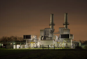
AIV Fundamentals At what pipe diameter and wall thickness should one be concerned about AIV? What is the relevant D/T ratio? This depends on the
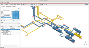
ON-DEMAND 🕖 3 SESSIONS x 45 MIN 🌏︎ ENGLISH Complete Pulsation Analysis Using BOSpulse Tim Gebraad Software Lead Engineer Marienne Faro Software Sales Engineer

ON-DEMAND 🕖 60 MIN 🌏︎ ENGLISH Getting the Timing Right: Why Time Step Size Is Critical In Surge Analysis Dr. Ir. Erik Jan
ON-DEMAND 🕖 30 MIN 🌏︎ ENGLISH Protecting Tank Terminal Assets Through Surge and FFS Analyses Thijs Krijger Project Engineer Katrine van Overhagen Engineer

ON-DEMAND 🕖 60 MIN 🌏︎ ENGLISH Choosing the right GRE piping standard: a comparison of ISO 14692 and ASME NM.2 Edwin Schimmel Project Engineer

ON-DEMAND 🕖 50 MIN 🌏︎ ENGLISH How Stepless Capacity Control Shapes Flow and Pulsations Thijs Krijger Project Engineer Get instant access Free. Recording

ON-DEMAND 🕖 60 MIN 🌏︎ ENGLISH Water Hammer Analysis & Mitigation in Pipeline Systems with BOSfluids Dr. Ir. Erik Jan Lingen Software Director

ON-DEMAND 🕖 60 MIN 🌏︎ ENGLISH Water Hammer Analysis & Mitigation in Pipeline Systems with BOSfluids Dr. Ir. Erik Jan Lingen Software Director

ON-DEMAND 🕖 35 MIN 🌏︎ ENGLISH Understanding, Modelling, and Managing Thermal Bowing using CAESAR II David Tickner Senior Engineer Get instant access Free.
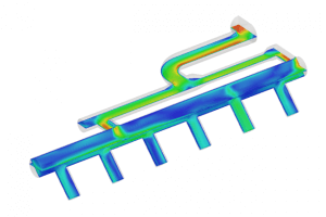
What are the key challenges in applying CFD to simulate and optimize multiphase processes in complex industrial systems? The main challenge here is the ability

Do CAESAR II formulas for thermal bowing and output results match with FEA? Short Answer: There can be significant differences between the results of CAESAR II and FEA.Explanation:The
ON-DEMAND 🕖 35 MIN 🌏︎ ENGLISH Using CFD for optimizing multiphase process engineering Bart van der Zalm Senior Engineer Get instant access Free.

DRG CONFERENCE – 35TH ANNIVERSARY 🌏︎ ENGLISH Innovations that Change the Engineering Industry Get instant access Free. Recording + slide deck available Event Description

ON-DEMAND 🕖 35 MIN 🌏︎ ENGLISH Fatigue Assessment According to ASME B&PV VIII Div.2 Lukas Bajarunas Senior Software Engineer Get instant access Free
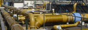
ON-DEMAND 🕖 45 MIN 🌏︎ ENGLISH Fiberglass Piping Stress Envelope According to ISO 14692 using CAESAR II Edwin Schimmel Project Engineer Get instant
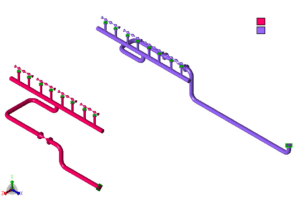
The station model of the Winksele Compressor Station, to be built in Belgium, was divided into two models with some mutual overlap, a compressor model and a filter model, each covered by a separate stress report. A third report covers the gas air coolers as model C, an add-on to
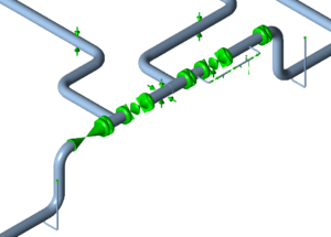
An additional separator was installed in Phase 2 of a cluster project and was to be connected to the existing lines through a modified above-ground (A/G) manifold. The manifold also connects to an existing buried (underground, or U/G) line. The analysis applied pressures of 100 / 225 Barg and temperature
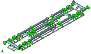
A combined CAESAR II model of a gas metering skid and its structural steel frames was assessed against ASME B31.3 (2006). The piping stresses were below the allowables, the steel stresses were within the allowable limits for the sustained and expansion load cases, and several bolt shear loads exceeded the
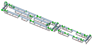
Multi-Mode Metering Skid with Undefined Connecting Piping The unit assessed was a 24-inch, 300# ethane metering skid. Gas can be routed through a normal operating line (line 1), a testing and maintenance line (line 2), two flow control lines (lines 3 and 4) and a bypass. No more than one
CAESAR II stress analysis of 13 critical sections of a buried GRP fire water system, to ISO 14692, expected no problems for the underground piping under pressure and temperature loads. High stresses occurred in vertical above-ground GRP pipes where the pipe is vertically restrained; in section D, guide and rest
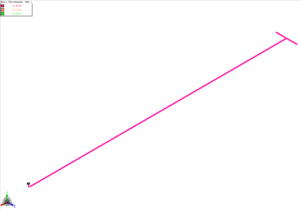
Seventeen underground GRE firewater subsystems at a degassing station were analysed in CAESAR II for three load cases, hydrotest, operational and sustained, to ISO 14692. It may be concluded that, upon implementation of the recommendations, the static pipe stresses are acceptable and the flange loads are moderate. Underground GRE Firewater
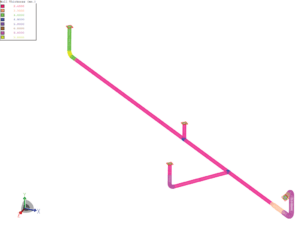
Thirteen buried GRE firewater subsystems were modelled in CAESAR II and assessed to ISO 14692 for hydrotest, operating and sustained load cases. On implementation of the recommendations, static pipe stresses are acceptable and flange loads are moderate. The buried glass-reinforced epoxy (GRE) piping in the firewater system upgrade at a
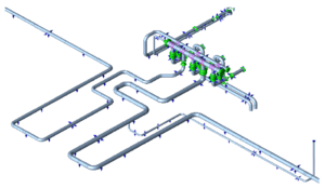
The main firewater line for a new oil terminal jetty is made from glass reinforced epoxy (GRE) pipe. It starts at the onshore transition between underground and above-ground pipe, where it connects to steel lines, and follows a jetty about 1.5 km long. A firefighting platform about one third of
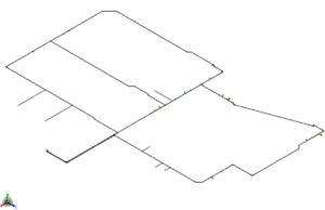
Static stress analysis of two buried GRE firewater subsystems in CAESAR II covered three load cases with a design pressure of 13.4 barg and a maximum design temperature of 40 °C. The stress analysis report, a preliminary issue, records wall thickness increases and polystyrene on five isometrics and concludes that,
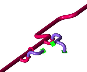
Nine underground GRE firewater systems, 77 stressed isometrics in total, were analysed in CAESAR II against the ISO 14692 allowable stress envelopes, with soil-pipe interaction modelled to the American Lifelines Alliance (2001) soil model. Modifications included a support bracing, polystyrene foam, NBR gasket stiffness limits and additional laminate for a
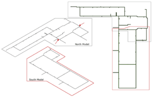
A CAESAR II static stress analysis of a buried GRE firewater network against ISO 14692 found 18 bends and 10 tees overstressed in the original design. In the modified models, all stress points are within the ISO 14692 envelopes for the sustained, operational and hydro load cases, provided the system
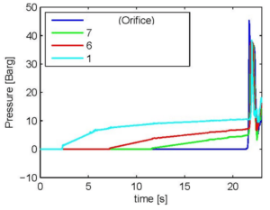
An underground storage station was being expanded with an additional compressor and a third injection well cluster, and the existing firewater package was being extended as part of the project. Two jockey pumps pressurise the system. When a blowout alarm is raised, the deluge valves open and the main firewater
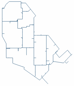
A buried GRE fire water ring was assessed in CAESAR II against the ISO 14692 allowable stress envelope. Static stresses stayed within the envelope for all load cases after additional lamination at nine bends, and the settlement analysis set a 4 MPa axial margin on the operational or occasional envelope.
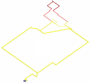
A new unit was added to an existing gas complex, and the firewater ring main was extended to serve it. Three sets of four 3-inch hydrant valves were modelled, twelve hydrants in total. Each hydrant is required to produce a minimum of 1452 l/min at 7.0 barg, and the hydrant
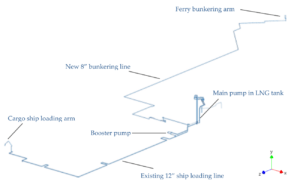
Extending an LNG terminal with a new cryogenic bunkering line At an LNG storage and loading terminal, a new line was constructed to supply liquefied natural gas directly to ferries. This 8-inch bunkering line branches from an existing 12-inch line that is used to load LNG into cargo ships. A
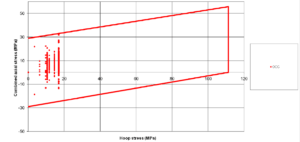
Surge loads from deluge valve closure were applied to nine composite firewater deluge systems in a CAESAR II time-history analysis and checked as occasional stresses against the ISO 14692 envelope. With three axial stops added in S4, all stress points lie within the envelope; the highest of the nine Smax
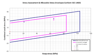
Elbows replaced after hydrotest problems A 5-inch glass-reinforced epoxy (GRE) transportation line runs buried between two locations. It connects to above-ground steel piping at both ends and to a steel manifold at about halfway. In total there are four connections between GRE and steel. The line is designed for 150
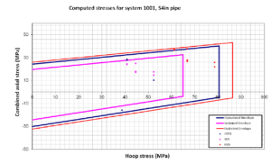
Buried Fibreglass Piping and an Undefined Compression Envelope The underground part of a seawater network at a gas field development was to be built in filament-wound fibreglass reinforced epoxy pipe buried in sand. The scope covered two systems, 1001 and 1002. Each system consists of a header of 54-inch and
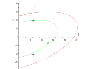
This project covered a family of glass fibre reinforced plastic (GRP) couplers, designated FWC, in five configurations: a DN600 coupler in a small (S) and a medium (M) variant, a DN1200 medium coupler, a DN2400 large coupler, and a DN3600 extra large coupler. Each coupler is a long cylindrical GRP
Technical Evaluation of Three Candidate GRP Pipe Suppliers For a glass-reinforced plastic (GRP) pipe system on a project, the client selected three potential GRP pipe suppliers, each to be evaluated from a technical perspective. Each supplier submitted a set of technical documents describing its component design, qualification testing and system
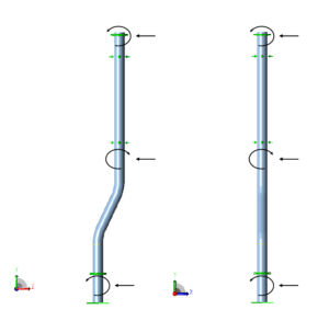
A seawater dump caisson made of glass-reinforced epoxy (GRE) needed its wall, laminate and joint details defined. The task was to find thicknesses and bonding lengths that would keep stresses within the allowable stress envelope conforming to ISO 14692, and to determine the loads that the restraints, flanges, laminated joints

DYNAFLOW RESEARCH GROUP (“DRG”) Enters into Reseller Agreement with Quality Professional Software (“QPS”) RIJSWIJK, The Netherlands – January 24, 2024 (Dynaflow Research Group BV) –

Dynaflow Research Group and Seawind Ocean Technology announce collaboration focusing on technical readiness of floating offshore wind applications in the Mediterranean Sea. This landmark partnership